3
\$\begingroup\$

What is an efficient method to detect the presence of Line AC power in an isolated method?

My first thought would be to use an optocoupler, but in order to do that, you need to supply the current needed. Placing a diode in series would make it only activate on half of the signal and save power. For example if you need 20mA to drive the optocoupler you would use resistors to limit the current. When you multiply 20mA by 120 or 240V you get 1200 or 2400 mW which is not efficient.

What other methods can be used to detect the presence of the voltage in an more efficient manor without using a step down transformer to get a lower voltage? My goal would be to get a circuit that uses limited power and common components.


I am sure someone is going to try and mark this as a duplicate of the many other 120VAC detection questions, but in this one I am looking for a more efficient method while still achieving the isolation.

Also the reason I do not want to use a transformer is due to the cost and component size as most transformers are not meant for only a few mW.

\$\endgroup\$
3
  • \$\begingroup\$ Battery-powered AC voltmeter? Resistor/diode/d'Arsonval meter AC voltmeter? AC powered relay? If there is an efficiency requirement, what is it? \$\endgroup\$
    – Whit3rd
    Commented Jul 19, 2016 at 3:17
  • \$\begingroup\$ Semi duplicate of link below. I would add some resistance and not just AC couple because high voltage spikes and surges will blow the LED in the optoisolotor. electronics.stackexchange.com/questions/150588/… \$\endgroup\$ Commented Jul 19, 2016 at 5:11
  • 1
    \$\begingroup\$ See neon lamp opto-isolator. \$\endgroup\$
    – Transistor
    Commented Jul 19, 2016 at 6:28

2 Answers 2

9
\$\begingroup\$

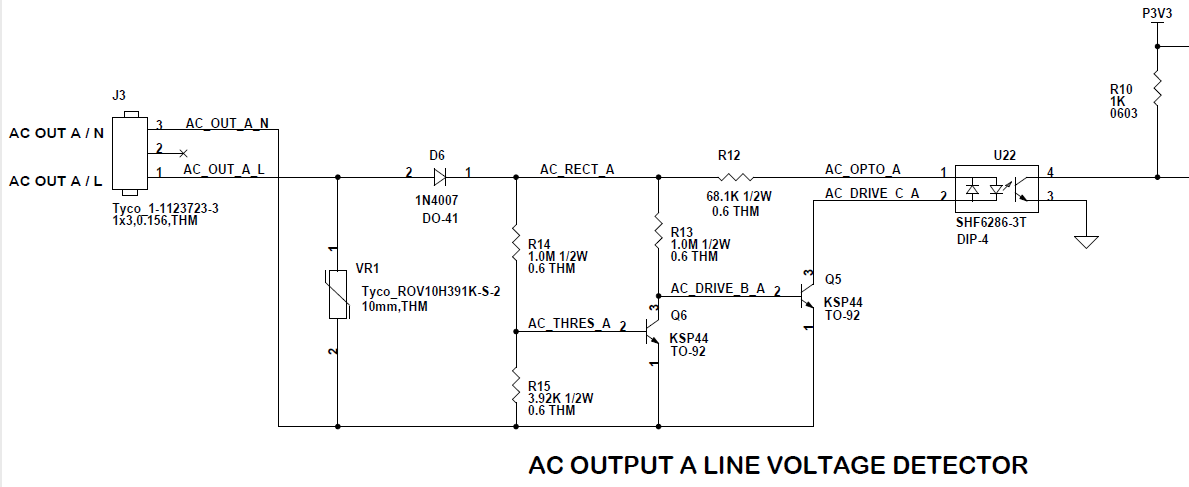
Here is how I have dealt with AC line detection in an efficient manner using an isolated opto-coupler. Key attributes of the circuit:

  1. The selected opto-coupler is one with a low forward current requirement
  2. The circuit works on either 120 or 240VAC systems
  3. The KSP44 transistor is high voltage type
  4. The transistor function is to cut off drive to the opto-coupler input diode when the AC voltage rises above a certain level thus limiting overall power dissipation
  5. The circuit design ends up outputting a pulse at each zero crossing
  6. The design shown was used in a commercial product that passed safety inspections by a government approved safety inspection agency.

enter image description here

\$\endgroup\$
2
\$\begingroup\$

The key to efficiently using an optocoupler is to run the optocoupler at a lower drive level -- it's possible to get sub-1mA on a routine 4N25 using a large value pullup resistor on the output into an HCMOS gate input on the isolated side to buffer the signal, and more sophisticated optocouplers can run at that current level or lower still. Look at the Current Transfer Ratio (CTR) specification in your optocoupler's datasheet, and also minimize leakage currents on the output side (this is why CMOS exists).

\$\endgroup\$
4
  • \$\begingroup\$ But even at 1mA, at 240V you will be still dropping .24W if it is on all of the time, or .12W if it is on half of the time. \$\endgroup\$ Commented Jul 19, 2016 at 11:22
  • \$\begingroup\$ @EricJohnson -- a quarter-watt opto circuit pulls 2.1kWh of power when run for an entire year, 24/7. It wouldn't surprise me if Michael Karas' circuit is even more efficient than that. In other words, we're already down in the chump-change level... \$\endgroup\$ Commented Jul 19, 2016 at 11:41
  • \$\begingroup\$ Make that an energy of 2.1 kWh. \$\endgroup\$
    – Transistor
    Commented Feb 3, 2021 at 8:08
  • \$\begingroup\$ @Transistor -- you're right, thanks \$\endgroup\$ Commented Feb 3, 2021 at 12:37

Your Answer

By clicking “Post Your Answer”, you agree to our terms of service and acknowledge you have read our privacy policy.

Not the answer you're looking for? Browse other questions tagged or ask your own question.