0
\$\begingroup\$

In a small board where space is important I need to place ESD protections near some 3.3V bus with I/O lines (4 pin: 3.3V, GND, digital input, digital output).

The most sensitive IC to protect is an xmega32A4. I'm going to use a USBLC6-2SC6 due to its very small package. I'm concerned about clamping voltage: using standard bidirectional 3.3V TVS, the clamping voltage can be as low as 5.7V @ 10A (example SD03C) while USBLC6-SC6 offers only 17V @ 5A.

How can I decide if this is enough or not? Is there any information in the xmega datasheet that I can use?

\$\endgroup\$

1 Answer 1

1
\$\begingroup\$

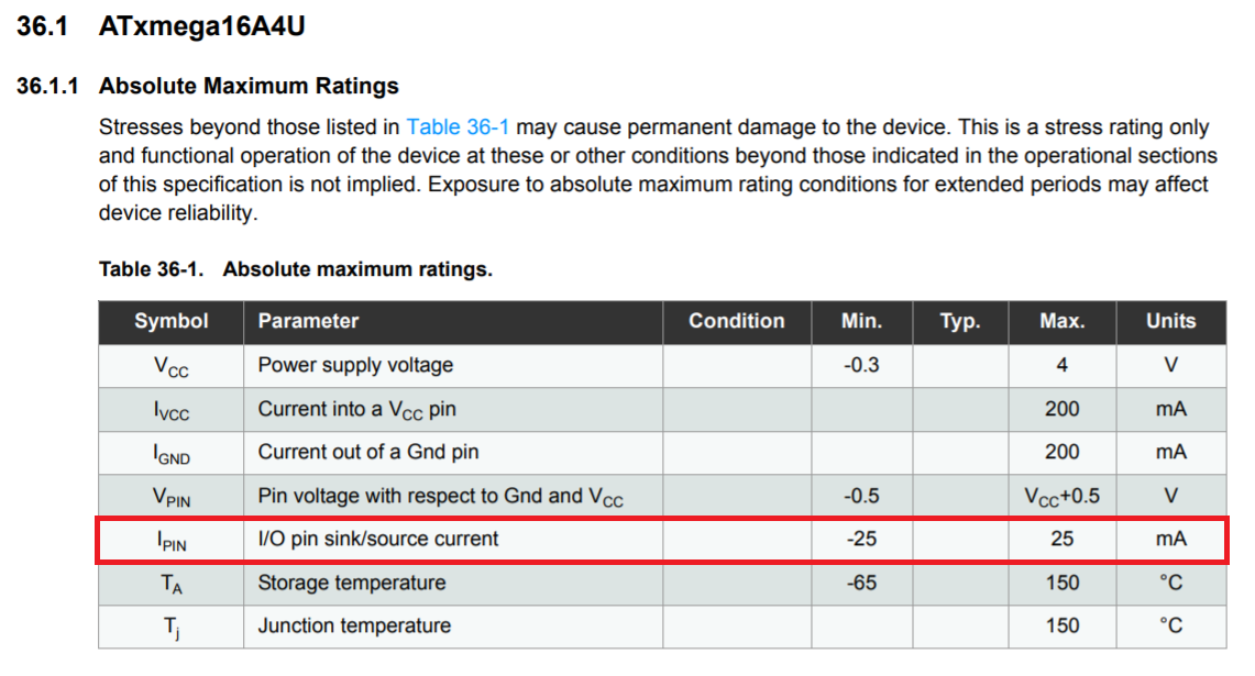
Read this first: -

enter image description here

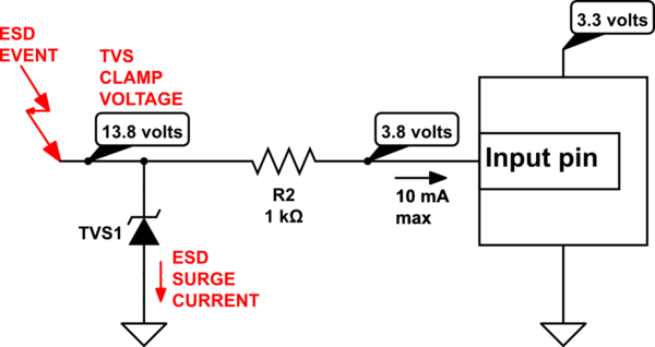
So, you can inject current into an input or an output providing that you do not exceed 25 mA. If your input bus line is protected by a TVS diode then, between TVS diode and the actual input pin you place a resistor: -

schematic

simulate this circuit – Schematic created using CircuitLab

The TVS has to clamp to no more than 13.8 volts to ensure that no more than 10 mA will flow into the pin.

So, choose how much current you want to allow into the pin under ESD events and insert a resistor between pin and TVS then, do the ohm's law math.

\$\endgroup\$
9
  • \$\begingroup\$ Got it, thanks! Should I apply this principle always? Example, pt100 connected to an ADC (MCP3426). The ADC allows 2 mA for input pins... but adding resistors changes the readings (if not 4-wires). Are there alternatives for this case? \$\endgroup\$
    – Mark
    Commented Feb 13, 2021 at 14:19
  • \$\begingroup\$ I'm not going to generalize on this. You can apply the principle whenever it might be necessary. As for your pt100 scenario, there isn't enough clear information in what you said to make a recommendation let alone recommend alternatives. Remember this is a Q and A site and questions should not evolve too much from the main formal question. I mean, what if you described it better and I said yes, that should work and then, 5 minutes later you say "what about this different scenario". Where we we stop so, on principle, I tend not to answer fairly unrelated follow-up questions. \$\endgroup\$
    – Andy aka
    Commented Feb 13, 2021 at 14:25
  • \$\begingroup\$ Sorry, I didn't want to annoy you. I apologize. I will never comment again a question asking a different scenario. \$\endgroup\$
    – Mark
    Commented Feb 13, 2021 at 14:44
  • \$\begingroup\$ @Mark please don't over react. I cannot actually comment on what you said because it's too under specified and I can't follow what you say because, adding resistors, as far as I can tell, doesn't change the readings. So, you must be thinking of a scenario I cannot picture hence, I cannot comment. But I do tend to find getting into these discussions leads from one thing to another. \$\endgroup\$
    – Andy aka
    Commented Feb 13, 2021 at 16:06
  • \$\begingroup\$ @Mark are we done here? \$\endgroup\$
    – Andy aka
    Commented Feb 15, 2021 at 16:07

Your Answer

By clicking “Post Your Answer”, you agree to our terms of service and acknowledge you have read our privacy policy.

Not the answer you're looking for? Browse other questions tagged or ask your own question.