0
\$\begingroup\$

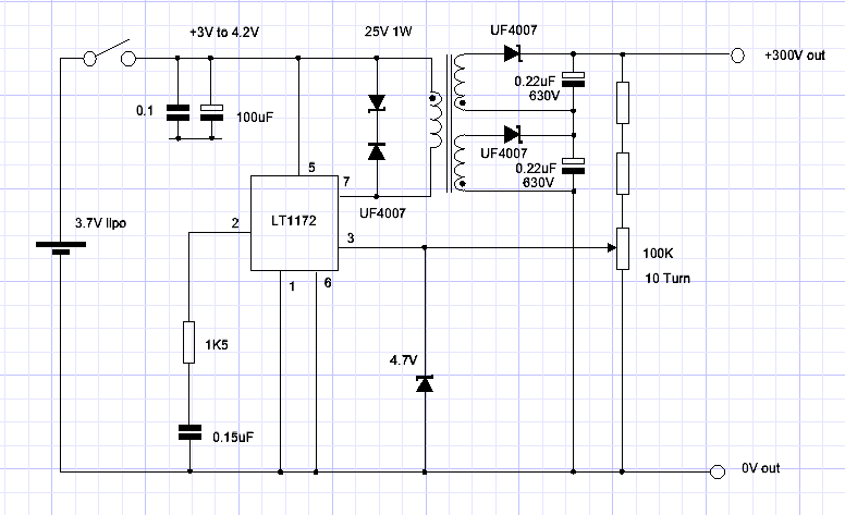
I’m building a circuit around an LT1172 to deliver 0-300 V from a USB charged LiPo cell. I’ve included the circuit.

LT1172 circuit

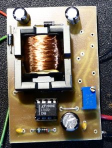
LT72 pcb

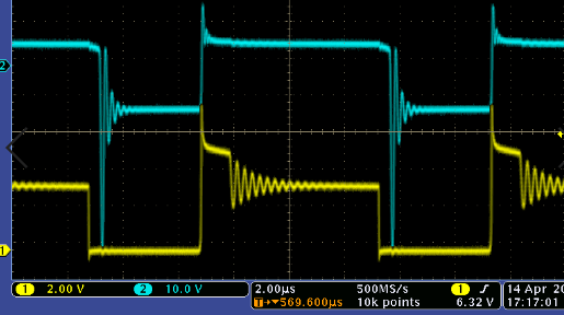
LT1172 waveform

I’m using an EPCOS EFD20 former with E87 cores (0.3 mm gap).

If I just have one of the output windings the circuit works like a charm, with an arbitrary 200 turns on a single secondary I get a solid 140 V into a 45 K resistor which together with the 100 K feedback pot works out at just over 0.6 W and holds line regulation between 3 V and 4.2 V input and load regulation doesn’t budge, efficacy is 65 % which I think isn’t too shabby, it also adjusts from 300 V down to 1.25 V, with a 2.4 V Zener in series with the output I can get 0-300 V, I couldn’t ask for more.

Now the issue is when I wind the second secondary everything goes belly up. Both windings end up going down to 84 V, I can tweak these back up to 130 V however I loose regulation and when I connect the two stacked outputs together the total voltage collapses further and the input current drops. Originally I used an online flyback calculator and entered the following:

100 kHz

Eff 60%

Al 0.25

Vin 3 V

Vout1 150 V

Iout2 0.0022 A

Vout2 150 V

Iout2 0.0022 A

This resulted in:

Lp 19 uH

Np 8.74 (9)

Ns1 659

Ns2 659

The 9 primary turns didn’t seem to put enough energy into the core and even a single 659 turns of secondary just killed the circuit, so I wound 19 turns on the primary (48 uH) and took a punt on 200 turns for the secondary which worked perfectly as mentioned.

Obviously the high number of turns on the secondary is causing the issue but I seem to have hit a brick wall and can’t get anywhere near my goal of 300 V.

I’ve built a few of these 300 V circuits before but used a XP A03P-12 which are very expensive and need a 12 V supply as well as not being adjustable.

Anyone know what I’m doing wrong?

edit. The core in the picture is separated, this is not how it was being used, I found by separating the cores I could get another 10 V of output.

\$\endgroup\$
1
  • 1
    \$\begingroup\$ Scope the primary current. This will tell you if you are saturating or if the current is rising to an acceptable level. If the energy isn’t going in then it won’t be coming out \$\endgroup\$
    – Kartman
    Commented Apr 26, 2021 at 9:20

1 Answer 1

1
\$\begingroup\$

so I wound 19 turns on the primary (48uH) and took a punt on 200 turns for the secondary which worked perfectly as mentioned.

OK with 300 volts on the output, the flyback voltage on the primary will be 300 volts * 19/200 = 28.5 volts.

But, you have a 25 volt Zener clamping that to probably around 26 volts and that seems likely to be a problem. Transformer action still holds in a flyback design. If the secondary peak voltage is 300 volts, that will be see as a flyback on the primary divided by the turns ratio reversed.

I'm not saying that's your one and only problem but it strikes me as being significant to your issues. If you have a 10:1 step up transformer and your output voltage is nominally 300 volts then, your Zener flyback catcher needs to be in excess of 30 volts (simple math).

\$\endgroup\$
3
  • \$\begingroup\$ Thanks Andy, reading my post back I probably didn't explain it as well as I could have, I actually have 2 outputs of 200 turns so guess that would be 150 Volts * 19/200 = 14.25 V each? I will check the zenor voltage, my diagram says 25V but the nearest I had was 24V, even so the wrong part may have been in the bag. \$\endgroup\$ Commented Apr 26, 2021 at 13:10
  • \$\begingroup\$ It looks like I will have to abandon this project as after spending 2 weeks on it I just cant justify any more time as other projects are falling behind. I've tried scoping the primary but the trigger has stopped working on the scope and nothing I do with the catch diode makes and difference. I tried using an off the shelf 4 v to 300 v transformer however I had exactly the same issue. The LT1172 just doesn't seen to like a high turns ratio. I'm going to go back to using an off the shelf HV converter but try something more elegant than a pot on its output to give 0 - 300 V. Thanks for your help \$\endgroup\$ Commented Apr 28, 2021 at 6:42
  • \$\begingroup\$ @RustyKipper if we are done here, please take note of this: What should I do when someone answers my question. If you are still confused about something then leave a comment to request further clarification. \$\endgroup\$
    – Andy aka
    Commented Oct 31, 2023 at 17:42

Your Answer

By clicking “Post Your Answer”, you agree to our terms of service and acknowledge you have read our privacy policy.

Not the answer you're looking for? Browse other questions tagged or ask your own question.