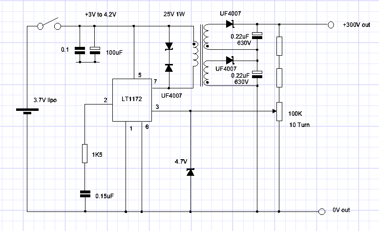
I’m building a circuit around an LT1172 to deliver 0-300 V from a USB charged LiPo cell. I’ve included the circuit.
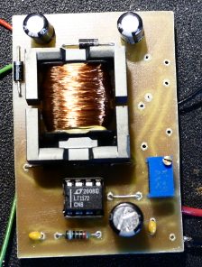
I’m using an EPCOS EFD20 former with E87 cores (0.3 mm gap).
If I just have one of the output windings the circuit works like a charm, with an arbitrary 200 turns on a single secondary I get a solid 140 V into a 45 K resistor which together with the 100 K feedback pot works out at just over 0.6 W and holds line regulation between 3 V and 4.2 V input and load regulation doesn’t budge, efficacy is 65 % which I think isn’t too shabby, it also adjusts from 300 V down to 1.25 V, with a 2.4 V Zener in series with the output I can get 0-300 V, I couldn’t ask for more.
Now the issue is when I wind the second secondary everything goes belly up. Both windings end up going down to 84 V, I can tweak these back up to 130 V however I loose regulation and when I connect the two stacked outputs together the total voltage collapses further and the input current drops. Originally I used an online flyback calculator and entered the following:
100 kHz
Eff 60%
Al 0.25
Vin 3 V
Vout1 150 V
Iout2 0.0022 A
Vout2 150 V
Iout2 0.0022 A
This resulted in:
Lp 19 uH
Np 8.74 (9)
Ns1 659
Ns2 659
The 9 primary turns didn’t seem to put enough energy into the core and even a single 659 turns of secondary just killed the circuit, so I wound 19 turns on the primary (48 uH) and took a punt on 200 turns for the secondary which worked perfectly as mentioned.
Obviously the high number of turns on the secondary is causing the issue but I seem to have hit a brick wall and can’t get anywhere near my goal of 300 V.
I’ve built a few of these 300 V circuits before but used a XP A03P-12 which are very expensive and need a 12 V supply as well as not being adjustable.
Anyone know what I’m doing wrong?
edit. The core in the picture is separated, this is not how it was being used, I found by separating the cores I could get another 10 V of output.


