0
\$\begingroup\$

I am doing a homework project, making an AC to DC converter using a rectifier circuit and regulator.

The homework conditions are:

We must use an AC input voltage with Vpp = 20V and frequency = 1kHz. We must get an output DC constant positive +9V or above.

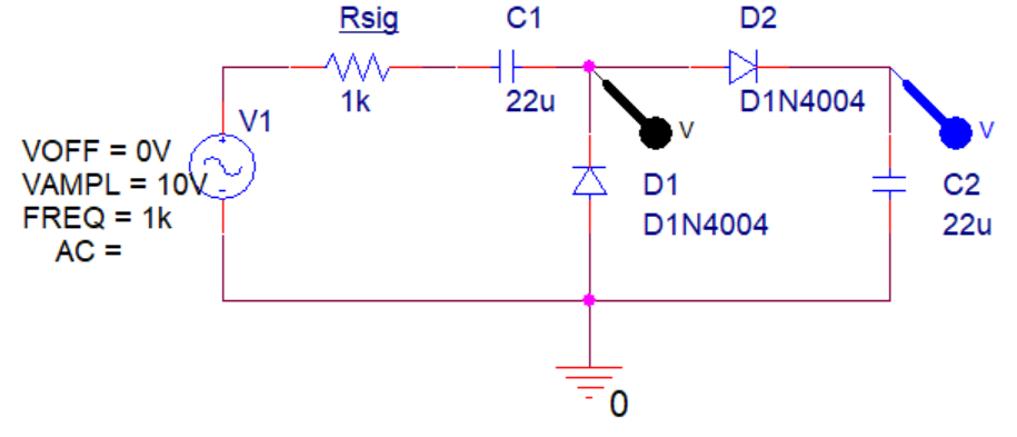
My thought (diagram) is

Input AC signal -> voltage doubler -> peak rectifier -> regulator

That is:

enter image description here

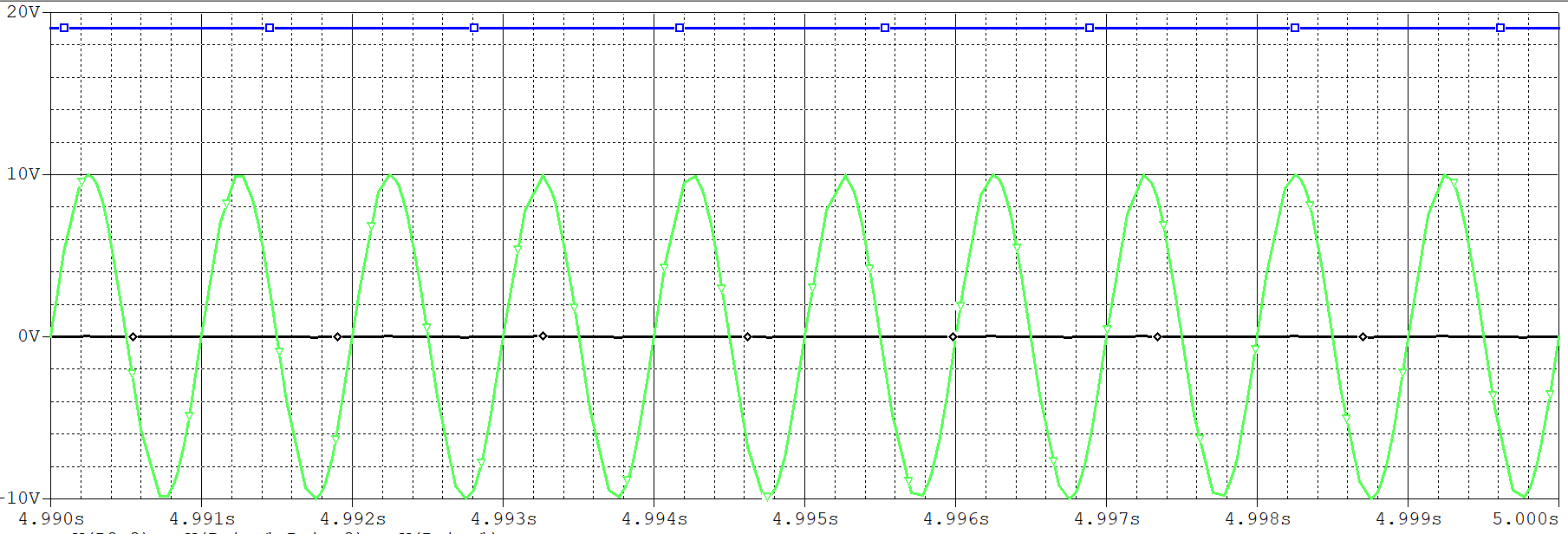
I measured the above voltage. This is the result:

enter image description here

Good result. Right? So I connected an LM7812CT to node C2. Like this:

enter image description here

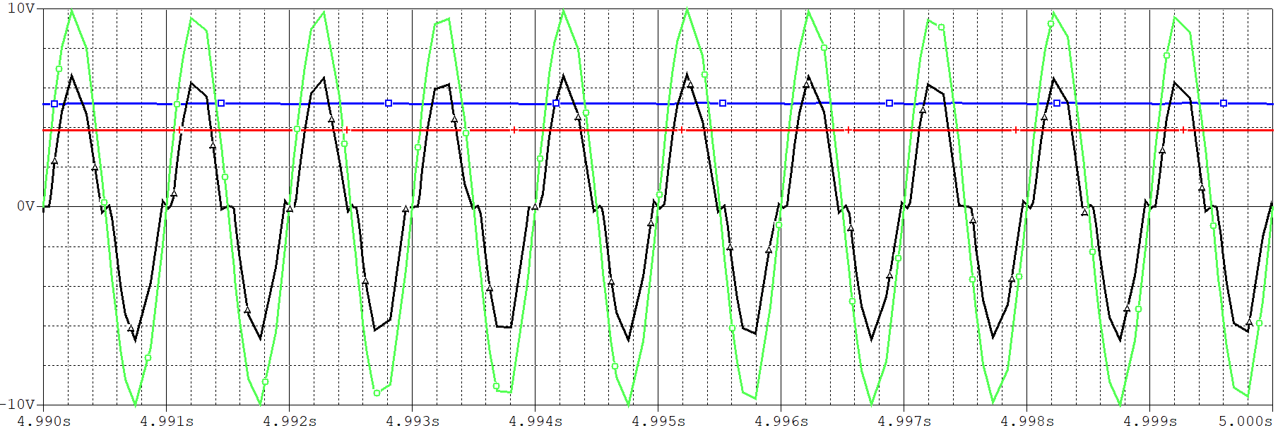
The problem is here. The measured voltage graph looks like this:

enter image description here

What? The input voltage to the voltage regulator drops a lot. I can't get the result what I want. I found that Rsig (power supplier resistance) has much voltage so the input voltage to voltage regulator is very low.

Why does this happen? I think that the input voltage regulator is very small so voltage dividing makes this situation, but it's not clear.

I want to know the reason for the voltage drop.

\$\endgroup\$
14
  • \$\begingroup\$ why do you do a voltage doubler if your V_in_pp is already higher than your V_out = 9V? \$\endgroup\$ Commented Jun 7, 2021 at 7:10
  • \$\begingroup\$ Because i guess that i must make an input voltage to Voltage regulator higher than 12V. \$\endgroup\$ Commented Jun 7, 2021 at 7:16
  • \$\begingroup\$ Have you considered using a "bridge rectifier" circuit? Maybe your AC input voltage is "floating" (like a winding from a transformer would be) so there's no need to connect one side of the AC source to ground. Why is there a 1 k ohm series resistor, it limits the current and wastes power. \$\endgroup\$ Commented Jun 7, 2021 at 7:19
  • \$\begingroup\$ Yes, i try many cases : using transformer.. using bridge rectifier.. But! it appears similar result. Rsig has many voltage!! The reason why i consider Rsig is... \$\endgroup\$ Commented Jun 7, 2021 at 7:21
  • 1
    \$\begingroup\$ 12 V is your requirement. The actual problem statement said 9V, which is even less than half the V_in_pp, which makes everything easier. You're imagining problems that aren't there: build a boring bridge rectifier, capacitor, 9V voltage regulator, done. \$\endgroup\$ Commented Jun 7, 2021 at 7:21

2 Answers 2

1
\$\begingroup\$

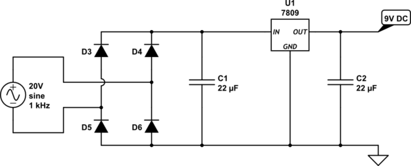
Like suggested in the comments, this will work much better:

build a boring bridge rectifier, capacitor, 9V voltage regulator, done

schematic

simulate this circuit – Schematic created using CircuitLab

This is a "classic" linear power supply circuit.

\$\endgroup\$
0
\$\begingroup\$

Welcome to EE stack exchange! The circuit should work, but the numbers are against you.

There's no perfect voltage regulator; the LM7812, for instance, draws approximately 8 mA of current for its internal amplifiers and voltage reference, so the 1 k ohm resistor will lose about 8V. The fact that your rectifier is a doubler, makes that 16V, and the capacitors are not zero impedance (22 uF at 1 kHz is about 7 ohms), so you can expect about another 20 ohms in two capacitors and two diodes. Lower that resistance, use bigger capacitors, and... it should work.

Of course, there's also usually going to be a load on the output, using that regulated power that your circuit provides. You want to simulate that, too.

\$\endgroup\$

Your Answer

By clicking “Post Your Answer”, you agree to our terms of service and acknowledge you have read our privacy policy.

Not the answer you're looking for? Browse other questions tagged or ask your own question.