2
\$\begingroup\$

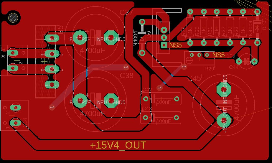
I have a circuit which purpose should regulate to voltage down to at least 3V. But when I try to adjust the 5kΩ potentiometer I only get minimum 14V voltage drop. I have a transformer which goes to bridge rectifier and my circuit input voltage is 19V DC after the rectifier. So I am very curious that why I can not arrange the voltage drop to less than 14V. You can find the specific information about my circuit and also schematic and pcb drawings down below.

Transformer: 220V AC/ 15V AC 2A LM338T Input Voltage: 19V DC

My doubts:

  1. In LM338T datasheet it has a circuit diagram which LM338T input voltage is minimum 28V DC. So is that why I can not get the voltage I want?
  2. LM338T is 5A regulator. I have max 2A input.

I tried to change the resistor values but nothing changes. Let me know what you think.

[UPDATE] I used 120Ω 1/4 watt resistance but resistance burned. That's why I am using 5 resistance as a paralel. I don't have any 120Ω resistance left so when i get some i will update this topic.

Schematic Design of The Circuit PCB Design of The Circuit

\$\endgroup\$
10
  • 1
    \$\begingroup\$ Are you sure you have a 5k pot fitted? \$\endgroup\$
    – Andy aka
    Commented Jun 28, 2023 at 12:15
  • \$\begingroup\$ Yes pot is 5kΩ. I am sure about that. \$\endgroup\$
    – REW
    Commented Jun 28, 2023 at 12:37
  • \$\begingroup\$ The only idea I have is a 180° rotated regulator IC. Does it regulate the 14 V under various loads? \$\endgroup\$
    – Jens
    Commented Jun 28, 2023 at 13:14
  • 1
    \$\begingroup\$ I connected a 12V 0.28A fan. And the voltage was 9V. \$\endgroup\$
    – REW
    Commented Jun 28, 2023 at 14:20
  • 1
    \$\begingroup\$ Did the 120 ohm resistor burn in this circuit? This should be impossible because we can expect here 12 mW power dissipation. This failure can give a hint about what is going on here. What are the voltages at IN, OUT and ADJ if the fan is connected? \$\endgroup\$
    – Jens
    Commented Jun 28, 2023 at 23:33

3 Answers 3

1
\$\begingroup\$

My doubts:

  1. In LM338T datasheet it has a circuit diagram which LM338T input voltage is minimum 28V DC. So is that why I can not get the voltage I want?

  2. LM338T is 5A regulator. I have max 2A input.

  1. The diagram you are referring to is a specific example. For that example the minimum input voltage is 28V because that is an example of a 25V regulator (as stated in the figure caption). Section 6.2 of the datasheet says you need a Vin that is at least 3V higher than Vout and the max difference is 40V. In your case you have a 19V input so you cannot output more than 16V.

  2. no problem

\$\endgroup\$
4
  • \$\begingroup\$ Unfortunately I don't have any option to change the input voltage but I get what you are saying. I was also looking for an LM317 voltage regulator as a solution to this. Will my problem be solved if I use this IC instead of LM338? \$\endgroup\$
    – REW
    Commented Jun 28, 2023 at 20:09
  • \$\begingroup\$ You don't need to change the input voltage. With a 19V input you can output 16V or less. You should be able to get the output down to 3V with your 19V input. I don't see a reason that switching to the LM317 would fix your problem. I'm not sure why you are not able to regulate down to 3V. Did you build this on a breadboard? As others have indicated this may be a wiring issue. \$\endgroup\$
    – WRG
    Commented Jun 28, 2023 at 20:32
  • \$\begingroup\$ You updated that: "[UPDATE] I used 120Ω 1/4 watt resistance but resistance burned. That's why I am using 5 resistance as a paralel. I don't have any 120Ω resistance left so when i get some i will update this topic." It is possible that when you destroyed your 120Ohm resistor you also damaged the regulator. I would swap it out. Also five 1k resistors in parallel is 200Ohm not 120Ohm. \$\endgroup\$
    – WRG
    Commented Jun 28, 2023 at 20:36
  • 1
    \$\begingroup\$ If your 120 Ohm resistor burned, you have a wiring error - there should only be 1.25 volts across the 120 Ohm (or 5 x 1K) resistor. \$\endgroup\$ Commented Jun 28, 2023 at 20:43
0
\$\begingroup\$

After your update, in which you tell us that you burned out a 120Ω resistor between OUT and ADJ, this is very suggestive that your regulator is damaged.

Normally there is exactly 1.24V across that resistor, for a power dissipation of:

$$ P=\frac{V^2}{R}=\frac{(1.24V)^2}{120\Omega} = 13mW $$

That is tiny, not nearly enough to kill it. It implies that the regulator is dead, or you have something connected very differently from how it is shown in the schematic.

Perhaps you have D3 or D4 reversed? Either would result in an uncontrolled increase of regulator output.

\$\endgroup\$
2
  • \$\begingroup\$ For the schematic that I gave in this example, I measured the voltage between the 5 parallel resistors (1k each and equivalent resistance is 200Ω) which was 0.5V. This is way lower than 1.25V. D3 and D4 connected correctly to the circuit. I created a PCB about the circuit. This is where I am reading the values ​​from. \$\endgroup\$
    – REW
    Commented Jun 29, 2023 at 11:11
  • \$\begingroup\$ @REW 0.5V across D4 sounds like D4 is backwards. Not saying it is, but it seems like quite a coincidence. Easy to check, remove D4 (and possibly C17; they are optional). \$\endgroup\$ Commented Jun 29, 2023 at 12:54
0
\$\begingroup\$

I solved the problem by replacing LM338T regulator with LM317. When I look closer to the LM338 IC, I saw that manufacturer of the IC was ST. ST doesn't have any product as LM338. I got a conclusion that never buy electronic devices from somewhere you don't know.

[CHANGES]

  1. I replaced the R1 resistor value to 120Ω and the potansiometer value to 2kΩ.
  2. Replaced the LM317 instead of the LM338 IC.

[CONCLUSION]

Now I can get any voltage between 1.25V and the input voltage of the IC.

\$\endgroup\$

Your Answer

By clicking “Post Your Answer”, you agree to our terms of service and acknowledge you have read our privacy policy.

Not the answer you're looking for? Browse other questions tagged or ask your own question.