0
\$\begingroup\$

I am designing a water level sensor using two 2mm graphite rods about 10cm long. I have attached the leads for my schematic to the graphite rods using silver epoxy.
I am using an Arduino Pro Mini pin A0 for the input from sensor. and the following code.

float waterSensorInValue = analogRead(A0);
delay(10);
float waterSensorInValue2 = analogRead(A0);
delay(10);
float waterSensorInValue3 = analogRead(A0);
delay(10);
float waterSensorInValue4 = analogRead(A0);
delay(10);
float waterSensorInValue5 = analogRead(A0);
delay(10);
float waterSensorInValue6 = analogRead(A0);
delay(10);
float waterSensorInValue7 = analogRead(A0);
delay(10);
float waterSensorInValue8 = analogRead(A0);
delay(10);
float waterSensorInValue9 = analogRead(A0);
delay(10);
float waterSensorInValue10 = analogRead(A0);
delay(10);

float waterSensorInValueA = (waterSensorInValue+waterSensorInValue2+waterSensorInValue3+waterSensorInValue4+waterSensorInValue5+waterSensorInValue6+waterSensorInValue7+waterSensorInValue8+waterSensorInValue9+waterSensorInValue10)/10;

Serial.print (waterSensorInValueA);

I take ten successive readings from the sensor pin and then divide by 10.

Does anyone know how to get more precise reading as with a few decimal places?

The problem is that the sensor reading isn't consistent. Last night it was reading 682 when the filler started filling the pool. Two and a half minutes later is read 664 when the level had risen a little. Then 2.5 minutes later it was 657. After that it went up (relatively) for the next hour as it filled. When it shut off the water it was reading 663. Two hours later it read 690 and then 693 two hours after that. Eight hours later it is at 702 with no more water being added. The water temperature hasn't changed.

Can someone explain the reason for the level to drop when water was first added and then rise only to shoot back up after it has finished filling?

One reason could be the water being sensed was directly from the ground water source without being mixed with the pool water which could have more particulates increasing conductivity.

Any help would help.

I am using averaging to mitigate wave action. But still the reading fluxuate as much as three points. I am thinking of putting more time between the reading and putting a 10uf capacitor between the sensor and ground to smooth things out. Any opinion on this.

Thanks for any suggestions.

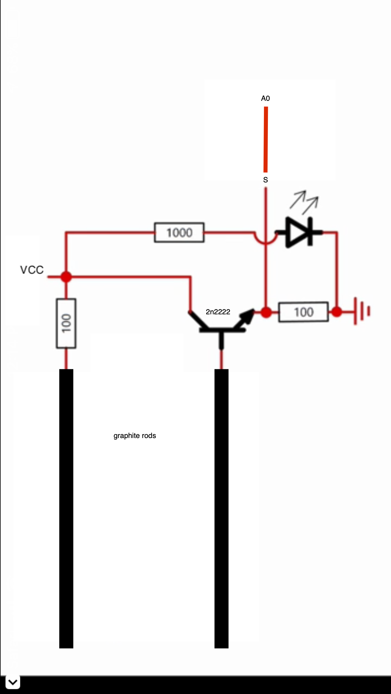
I am not including the led on my wiring.

wiring diagram for sensor

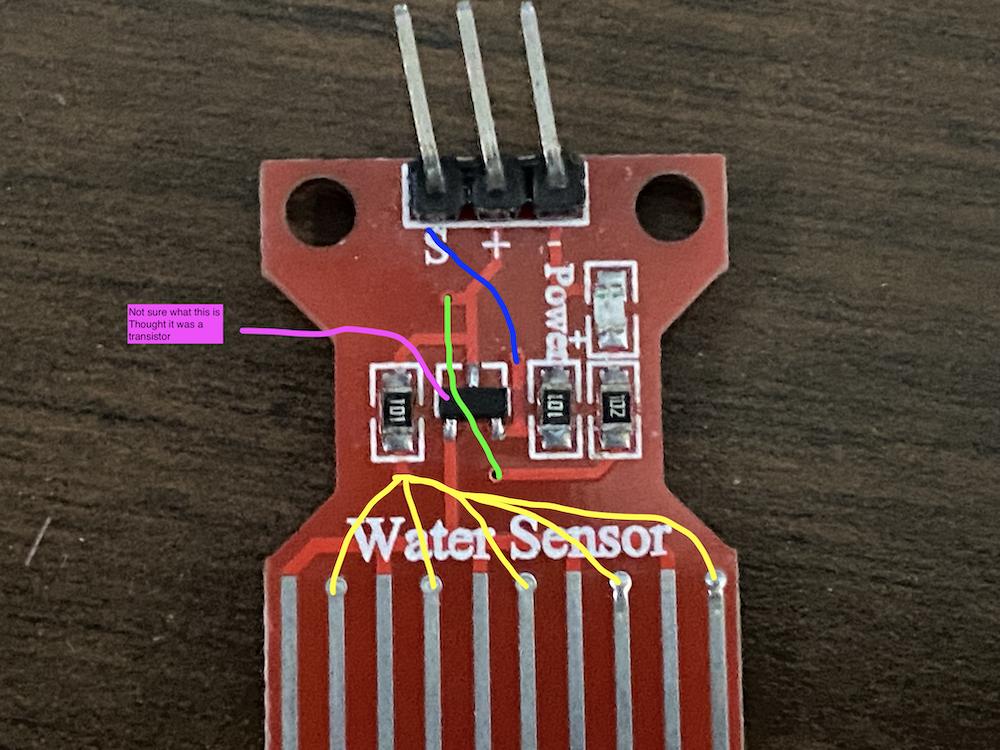
This is the MH Water Sensor I based mine on As the water rises up the bars the reading rises. Am I missing something or do I have the wrong type transistor?

water sensor

\$\endgroup\$
5
  • \$\begingroup\$ (1) Why are you using graphite? (2) Where did the circuit come from? (3) How do you think your circuit should work? (4) average = (average * 9 + analogRead(A0))/10; delay(10); should do the same job as your first 20 lines of code. \$\endgroup\$
    – Transistor
    Commented Jun 8, 2021 at 18:41
  • \$\begingroup\$ graphite does conduct electricity but doesn't corrode or build up deposits on it as easily as metals. I found it on line but also analyzed a red MH water sensor. \$\endgroup\$ Commented Jun 8, 2021 at 18:50
  • \$\begingroup\$ If the old water is mixing with fresh water who knows what you are going to read. You should probably use capacitive sensing rather than resistive. \$\endgroup\$ Commented Jun 8, 2021 at 19:36
  • \$\begingroup\$ I have 2 non-contact proximity sensor to turn water on and off. But would like to have a relative depth reading while filling and evaporation. \$\endgroup\$ Commented Jun 8, 2021 at 20:34
  • \$\begingroup\$ Would it make a difference if I had one rod coming up from the bottom. So it starts where the other one ends and goes up? \$\endgroup\$ Commented Jun 8, 2021 at 20:37

2 Answers 2

1
\$\begingroup\$

From your description It appears it is a tank open to atmosphere. If this is correct you can simply use a pressure transducer to determine the level in the tank. They have used this technique in washing machines for many years. There are many sensors available, you just want to use a differential one so the ambient pressure (atmosphere) pressure is taken out of the equation. Place the inlet tube to the pressure sensor into the tank until it just about reaches bottom. If there is no leak in the tubing you will have a reading.

\$\endgroup\$
0
\$\begingroup\$

Your problem is that the conductivity of water is not constant; it varies with pH, and dissolved gasses (CO2, for example) produce large effects. Temperature, too, modulates the reading. It might be better to use an AC-excited probe, and detect capacitance between your electrodes by the AC current that results; air and water have very different dielectric constants.

Try the detector in a beaker of tap water, and stir in a drop of vinegar, to see the effect.

The detection that the given circuit DOES do well, is not of level height, but simply of water contact with the probes.

\$\endgroup\$
7
  • \$\begingroup\$ but as the water gets deeper it contacts more of the probes so should give a higher reading correct? My big question why the big drop after water starts to fill and then big jump after it finishes filling? With a 30,000 gal pool the PH and dissolved gasses should change that much that fast, should it. \$\endgroup\$ Commented Jun 8, 2021 at 20:42
  • \$\begingroup\$ I can't use AC as the whole unit is DC powered. \$\endgroup\$ Commented Jun 8, 2021 at 20:45
  • \$\begingroup\$ Or is it that once the rods are contacted there is a reading no matter how much the water covers the rods/ However the MH water sensor gives a higher reading when more of the small rods of metal are covered by the water. Would more smaller rods work better? \$\endgroup\$ Commented Jun 8, 2021 at 22:21
  • \$\begingroup\$ @user1114881 It's easy to make AC; just connect a Schmitt inverter with resistor negative feedback, and the input pin to one electrode (other to ground). The frequency of the oscillation tells the capacitance. This works if R_feedback is low compared to the water's resistance, and the inverter is near the rod (wiring capacitance is an error source). \$\endgroup\$
    – Whit3rd
    Commented Jun 8, 2021 at 22:49
  • 1
    \$\begingroup\$ An additional problem with DC is electrolysis. Bubble of hydrogen and oxygen (or chlorine from dissolved salts) form on the electrodes, rapidly changing readings. Also, deposits build up on the electrodes from decomposition of other solids, such as carbonates. \$\endgroup\$ Commented Jun 9, 2021 at 0:10

Your Answer

By clicking “Post Your Answer”, you agree to our terms of service and acknowledge you have read our privacy policy.

Not the answer you're looking for? Browse other questions tagged or ask your own question.