13
\$\begingroup\$

Preface - I don't know much about electronics :P

I have ordered a Shimano dynamo hub for my bicycle. I have done a little homework and here are my findings about it:

  1. The output of the above mentioned dynamo is a 6 volt AC.

  2. The output voltage of the dynamo is not stable, it varies based on the speed of the dynamo.

  3. There are chances that the lights will blow up ;) Reason is because of non stabilized voltage output.

Based on the above I have few questions.

  1. Is there a simple circuit which converts AC to DC output? I have read about some bridge rectifiers, but wanted to be absolutely sure about it. Also what size is the circuit, how easily it is available and how reliable it is?

  2. Most important thing which I wanted to know, how do I built a circuit so that the 6 volt fluctuating AC output from dynamo to convert to a 5 volt (USB chargeable) stabilized DC output? Are there any already available? What is the cost of such circuit or how easily can I build from scratch?

  3. I have read somewhere that plugging in a device to a non-stabilized input source (in this case the 5 volt output from dynamo to my iPhone) would blow off the device. So, if I could not achieve in building (or purchasing) the above mentioned point 2's circuit, can I use the 5 volt output to charge intermediate batteries like a spare Lithium Ion solar charger for iPhone and a AAA rechargeable batteries through a USB charger and use these to charge up my gadgets?

\$\endgroup\$
6
  • 2
    \$\begingroup\$ cyclingabout.com/index.php/2012/03/… may be of interest - commercial devices that do this. \$\endgroup\$
    – pjc50
    Commented Feb 4, 2013 at 15:30
  • 1
    \$\begingroup\$ I think one device that can help is a buck boost combo IC. This will take over and under voltage, and output a stable voltage, as long as the current is there. Still, large capacitors would be needed to ensure more stability (perhaps you should just use it as a battery charger, and use the battery as primary source of energy). \$\endgroup\$ Commented Feb 4, 2013 at 17:35
  • \$\begingroup\$ Thanks guys, I would prefer charging an intermediate battery. I have both lithium ion solar charger + usb charger and AAA usb charger. But my concern is whether these charger circuits would also blow up due to fluctuating voltage? And also I still need a 6v AC to 5v DC convertor circuit I guess? \$\endgroup\$ Commented Feb 5, 2013 at 5:44
  • 1
    \$\begingroup\$ An example of someone building this with a bridge rectifier and a simple regulator: instructables.com/id/… \$\endgroup\$
    – pjc50
    Commented Feb 5, 2013 at 15:30
  • \$\begingroup\$ Did the dynamo you ordered four years ago have just been delivered? Wow, that's not what I'd call express shipping... More seriously, are you looking for a simple solution using premade modules, or something you build all by yourself with discrete components? \$\endgroup\$
    – dim
    Commented Jan 6, 2017 at 21:07

6 Answers 6

7
+50
\$\begingroup\$

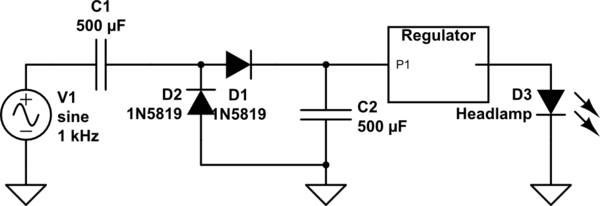
Don't use a bridge rectifier. It's inefficient, because you need two diode drops in series, and it doesn't allow you to use the frame as ground for a DC lamp (like, a modern LED bike light). Instead, consider a voltage doubler

schematic

simulate this circuit – Schematic created using CircuitLab

The 'regulator' can be a current regulator, or just a Zener followed by a limit resistor. Several LEDs in series can make use of the 'extra' voltage supplied. Accuracy, like efficiency, is less than important in this application.

I've used a 6V sealed lead-acid battery as the 'regulator'; overcharging seems not to be a problem, and a low-dropout regulator IC can ensure that the output to the lamps is a stable 6V.

Charging from a '5V' source is possible, but depending on such things is less than satisfying; the generator has all the power you need.

\$\endgroup\$
7
  • \$\begingroup\$ If you use a voltage doubler without a DC to DC converter you will nearly double your losses in the regulator (such as a 7805). \$\endgroup\$
    – Voltage Spike
    Commented Jan 10, 2017 at 22:30
  • \$\begingroup\$ My original use was with a lead/acid battery, which had such low impedance that the 'doubling' didn't ever effect the output. With larger capacitors, a DC/DC regulator (stepdown) would be more efficient than zener or linear regulation. Smaller capacitors were my limit on battery charge current. \$\endgroup\$
    – Whit3rd
    Commented Jan 11, 2017 at 6:51
  • \$\begingroup\$ +1 for the CircuitLab simulation! (By the way, Falstad is the open source alternative) \$\endgroup\$
    – JinSnow
    Commented Jan 14, 2020 at 8:17
  • \$\begingroup\$ sorry but how do you simulate this circuit? (I clicked on the first link, then on the "simulate" button, it simply opens this panel i.imgur.com/gKVnHSO.png ) \$\endgroup\$
    – J. Does
    Commented Sep 15, 2020 at 13:20
  • 1
    \$\begingroup\$ @J.Does - That 'regulator' is just a placeholder; I used a battery with a voltage regulator in series for an incandescent lamp, but CURRENT, not voltage, regulation is the best way to drive an LED (or multiple LEDs in series). AMC7140 is an example of such a regulator, from China (ADDtek). \$\endgroup\$
    – Whit3rd
    Commented Sep 15, 2020 at 19:22
5
\$\begingroup\$

I have two of these dynamos (actually Schmidts, not Shimanos, but electrically they are equivalent), and have built a lot of led lights already.

I figured a configuration that is at the same time easy to build, safe, efficient and cheap. It has been intensively tested in daily use.

First of all, there is one important thing thing to care, from your question: you want an USB compatible output. This can be quite a problem, since electronic devices require a stable output. Suppose, for example, you want to charge your cell phone while riding: when you stop the bike, it will "turn off" the charging. When you start moving again, it will "turn on" the charging (and probably the phone will beep and turn the display on).

So in this case, you will need a more sophisticated circuit, most probably including a battery. I have never done that. Phill Frost explained it in detail already.

Now if you want just a LIGHTING circuit, then my current setup is working very very fine and is composed of:

  • Regulator: One 5W/6.8V Zener diode;
  • Filter/Stabilizer: One 16V 6800uF electrolytic capacitor;
  • Rectifier: Four rectifier diodes assembled as a bridge;

With this, I get a quite stable (above 5 miles per hour at least) and sharply regulated 6.8V output. The 6.8V instead of 6V is needed so that I can wire two white leds in series, which won't work since their voltage drop is slightly above 3V each.

Since the output of these dynamos is nominally 6V/3W, using a 6.8V/5W keeps the voltage controlled and loses very little current: most of the energy is drained by the LEDs you plug in.

And since the current is limited to 3W (0.5A), you won't blow the 5W Zener even if you run the system without any device attached (only small sparks of each wave cycle are actually above 6V, as I have checked with a friend's oscilloscope).

You can have the SVG schematic here:

https://gist.github.com/heltonbiker/6784ebdb864f61ff33ffa340dc9d294b

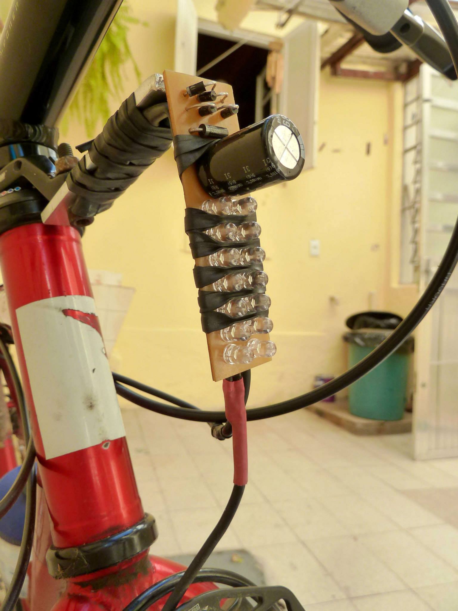
And the final thing (ugly but surprisingly rugged and weather-resistant) is below. Note that only the diodes and capacitor are what you want, but I assembled the LEDs on the same board because of personal preference for this project.

enter image description here

\$\endgroup\$
4
  • \$\begingroup\$ Unfortunately the dropbox link is broken \$\endgroup\$
    – Chris H
    Commented Oct 16, 2019 at 10:26
  • 1
    \$\begingroup\$ @ChrisH I reposted the SVG schematic as a GIST (see the link in the question). \$\endgroup\$ Commented Oct 16, 2019 at 13:33
  • 1
    \$\begingroup\$ @ChrisH also, please notice that I originally posted 6V as the target voltage, but it is actually 6,8V. This is needed so that the white LEDs can be wired pairwise in series without a resistor, and will work very fine. \$\endgroup\$ Commented Oct 16, 2019 at 13:37
  • \$\begingroup\$ nice! I'm amazed that that holds up in the rain though. \$\endgroup\$
    – danmcb
    Commented May 18, 2021 at 8:20
4
\$\begingroup\$

Is there a simple circuit which converts AC to DC output? Also what size is the circuit, how easily it is available and how reliable it is?

A bridge rectifier, as you mentioned. It's small, and easy to find, and quite reliable if operated within specifications. Any electronics distributor will have them. Since they are little more than a specific arrangement of four diodes, it's also not difficult to make one.

How do I build a circuit to convert the 6 volt fluctuating AC output from dynamo to a 5 volt (USB chargeable) stabilized DC output?

Any number of ways, but since this electrical power is coming from you, you probably want it to be efficient, and small, and light. That probably means a switched mode power supply. It's not a simple circuit to build, but as pjc50 mentions in a comment, there are commercial products that have done it already.

I have read somewhere that plugging in a device to a non-stabilized input source (in this case the 5 volt output from dynamo to my iPhone) would blow off the device.

That's exactly right. If your device was not designed to run off the voltage supplied by this hub, then it will most likely be damaged by it. Batteries also require a specific power supply to charge them. The supply voltage must be greater than the battery voltage, but not much, otherwise they are usually damaged. The specifics vary quite a bit between battery designs, but it's a safe assumption that connecting any battery directly to this dynamo will result in bad things.

My advice: since it's apparent from your question that you have little knowledge in electrical engineering, and what you want to accomplish is not trivial, stick to commercial products designed to work with that hub.

\$\endgroup\$
1
  • \$\begingroup\$ The man came here, like me, to learn something, I don't think suggesting to stick to commercial products is helpful. We all know these products exist, that's not the point. \$\endgroup\$
    – Alex G
    Commented Nov 8, 2019 at 23:28
2
\$\begingroup\$

I would suggest a full bridge rectifier, followed by a capacitor and a ready-made DC-DC step-down (buck) circuit. You can find many that are about 20x35x10mm big and each one cost about 2-5 dollars, shipment from Hong-Kong included.

The advantage of these buck regulators is that they take from the source only the energy they need, wasting little in heat, and therefore the "load" on your legs is as low as you can possibly get.

Any other solution that involves resistors (like a Zener regulator, or a linear regulator) will be less efficient.

The different solutions listed here are explained in this answer to the question "How to convert 6V AC to 5V DC?": a technical version of this question.

\$\endgroup\$
1
\$\begingroup\$

I've just built a regulator along these lines:

KBPC104 2A 200v Bridge Rectifier 470uF 100v electrolytic LM2596-based buck converter from e-bay

It seems to start charging immediately even with very slow rotation of the wheel and I can hear from the hub that it is fully loaded. My hub is a SON-delux so it is important that I can get output at low speed, particularly as I'll be riding in the mountains where sometimes I will be riding very slowly.

Also, my 22000 cache battery recognises the voltage immediately and starts charging.

My previous regulator used an LM317 and the cache battery would not recognise that it was charging probably because the voltage ramped too slowly.

I think this is a good circuit. Also the parts were very cheap.

I tried a Velo charger which can supply up to 1.5A but I found that the wheel had to be spinning very fast to get the unit to turn on the output. I returned it.

\$\endgroup\$
1
\$\begingroup\$

To maximise efficiency in this situation the circuit given by Whit3rd is the one to go for. He selected Schottky diodes because they have a low forward bias voltage drop and a voltage doubler circuit because it only involves putting one diode voltage drop between the AC input and the DC output. A standard bridge rectifier has a silicon junction diode forward bias volt drop of around 0.6V and puts 2 of those in series so takes out 1.2 V from the relatively modest 6V or so output from the dynamo. The voltage doubler ends up with quite a high voltage though, which you need to reduce and the most efficient way of doing this is to use a switched mode voltage converter, such as the MT3608, which is available for minimal costs wired up with the inductors, et cetera, on a small circuit board that has an output voltage adjustable by a potentiometer and an efficiency of over 90%. Voltage and current regulators do not work in the same way as a switch mode power supply, and provide a regulated output by using dropout in which the input voltage must be higher than the output voltage and the regulator fixes the output voltage over a wide range of input voltage with the same current flow into the regulator. That means that if for example, the input voltage is 12V and the output voltage is 6V, half of the power will be dissipated as heat in the regulator. Similar considerations apply to current regulators.

\$\endgroup\$

Your Answer

By clicking “Post Your Answer”, you agree to our terms of service and acknowledge you have read our privacy policy.

Not the answer you're looking for? Browse other questions tagged or ask your own question.