Background
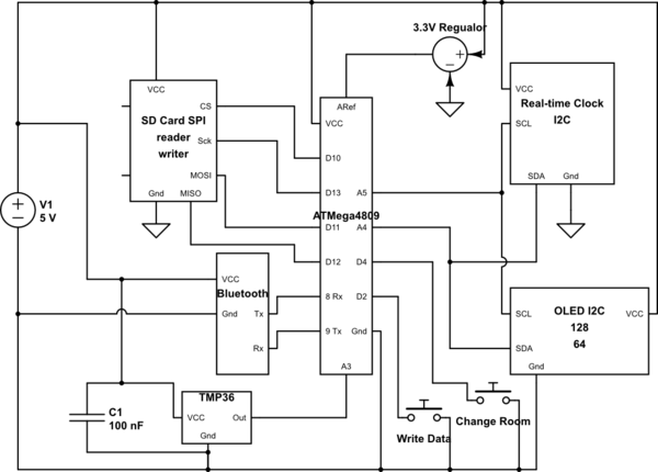
I have the following circuit built on a breadboard at this time.
I'm powering it off computer USB and a 5 V, 2 A wall wart (via USB) into the Nano Every (which is located on the breadboard -- making the ATMega4809 available).

simulate this circuit – Schematic created using CircuitLab
Reading temperature values
I'm reading temperature values from the TMP36 and writing them to an SD Card along with times and displaying them on the OLED screen.
Temperature values vary wildly
I'm using the following library to read temperatures ==> https://github.com/Isaacr100/TMP36
This is a good library and basically wraps up the simple functionality of converting voltage to temperature.
The getValues function is basically everything you need to know about.
void TMP36::getValues() {
  _value = analogRead(_pin);
  _voltage = (_value/1024.0) * _aref;
  _tempC = (_voltage - .5) * 100;
  _tempF = (_tempC * 1.8) + 32;
}
Main question
Why do my temperature values vary so wildly from one reading to the next (70.4°F up to 74.44°F)?
What I have tried
1. I built an entire test board which has 2 TMP36 components and a regular Arduino Nano (uses ATMega328). This board reads from two components on different Nano pins and writes the values to SD card so I can see how much they change -- also displays on an OLED.
Results -- are different
On this separate board, I see values that are much more in line with the actual room temperature (69 - 70°F) and they do not vary much at all -- within 0.5 - 1 degree of each other, but much of the time they are the same value.
2. I read the TMP36 datasheet and added 22 μF caps on the VCC / GND pins of all the TMP36 as they suggested and thought that would get better (for noise). This didn't help in my circuit that is shown.
3. Because this calculates temperature from voltage I decided it was important to insure that my voltage was very precise. I installed a 3.3 V voltage regular and checked with multimeter.
3.3V voltage regulator
Notice that I'm insuring that my reference voltage is good also, by running a 3.3 V regulator into AREF on the Nano Every and using analogReference(EXTERNAL).
This should insure that the temperature conversion is done in relation to a proper reference voltage.
I read the value off the regulator and I'm getting a solid 3.29 to 3.30 V.
I'm also passing thd proper voltage (3.29 V) into the TMP36 library (mentioned above).
Circuit shown varies -- other board doesn't
Since the test board has two TMP36 components on it, I've taken one out and swapped it with the one in the circuit shown but it varies wildy only in the circuit shown, but not the test board.
Why might this be?
What types of things should I look at now? Is this just because I have a lot of noise in this circuit?
NOTE: The two momentary buttons are wired properly for debounce but shown in the schematic as direct connect for simplicity.
