0
\$\begingroup\$

I have a Coherent Cx-10 CO2 laser that I want to use for laser heating of very small samples at high pressure, so I need to accurately control the laser power. I also have a pulse width modulated power controller, called the PC-1G, from the same company. This controller only has a knob for adjusting the laser power but it also has a 37-pin D-connector for user interface.

Power is controlled with a voltage input to control duty cycle, described in the operator's manual as: "It is possible to vary the average output power of the laser from zero to its maximum output by delivering to the laser RF power module a fixed frequency, variable duty cycle control signal". I believe the laser is protocol independent and duty cycle is adjusted with voltage to a single pin, so how do I control this voltage? It seems that the 37-pin connector is not commonly used, so I'm also wondering what kind of hardware I can use to interface with the PC-1G controller.

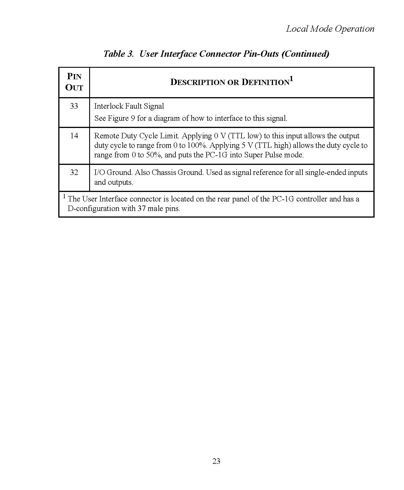
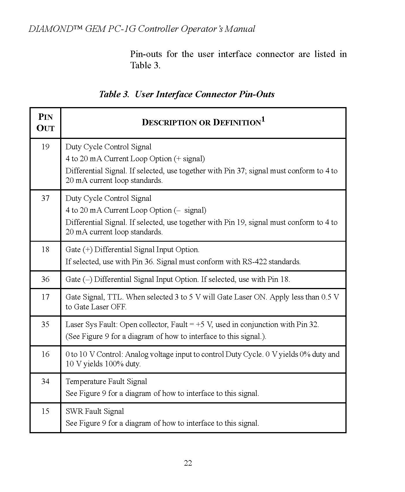
I attached the pin-outs for the user interface connector and I can attach the block diagram for this controller or anything else if it would help.

User Interface Connector Pin-Outs Page 1

User Interface Connector Pin-Outs Page 2

\$\endgroup\$
1
  • \$\begingroup\$ Have you successfully managed to control the power of the Coherent Cx-10 CO2 laser by connecting it to the PC-1G controller using the 37-pin D-connector for the user interface? I'm facing the same issue and have contacted Coherent, but I haven't received a response yet. If you've succeeded, could you please share how you did it? \$\endgroup\$
    – user441893
    Commented Oct 22 at 21:43

1 Answer 1

1
\$\begingroup\$

Looks like pin 16 is duty cycle input, and 32 is ground.

Now whether pin 16 is 0-10v input or PWM input, it can be that both can be used, i.e.,

  • 10VDC will produce 100% output.
  • 10VAC (squarewave) at 1kHz, 50% duty cycle, will produce 50% output.
  • 6VAC at 50% duty = 30% output, etc.

Of course, for the best response, contact the manufacturer.

\$\endgroup\$
4
  • \$\begingroup\$ The average optical power of the laser is determined by a "RF Enable" signal sent to the RF power module, with the "RF Enable" signal having a variable duty cycle that depends on the voltage to pin 16. Now, how can I control the voltage to pin 16? The manufacturer recommended using a programmable logic controller and could not offer any further advice. Will a PLC work or is there a cheaper option? \$\endgroup\$ Commented Jul 6, 2021 at 18:24
  • \$\begingroup\$ I think anything which outputs up to 10VDC at a low current, perhaps 0.1A, would likely work for pin 16. Most inputs don't consume much current. However unless this current (or input impedance) for pin 16 is specified, we are just guessing. Sometimes input current is specified, sometimes not. \$\endgroup\$
    – rdtsc
    Commented Jul 6, 2021 at 19:41
  • \$\begingroup\$ What is an example of something that could do that and how would I connect it to the pin? \$\endgroup\$ Commented Jul 6, 2021 at 20:03
  • \$\begingroup\$ You could find a 10VDC power supply and connect it. Or a variable DC supply, and be careful to not go over 10V. Or even a 9V battery just to test. Find a mating connector - sounds like a 37-pin d-sub connector but you'll have to investigate, compare datasheets, take measurements (with a caliper or micrometer) to make sure the connector will fit. \$\endgroup\$
    – rdtsc
    Commented Jul 6, 2021 at 20:34

Your Answer

By clicking “Post Your Answer”, you agree to our terms of service and acknowledge you have read our privacy policy.

Not the answer you're looking for? Browse other questions tagged or ask your own question.