0
\$\begingroup\$

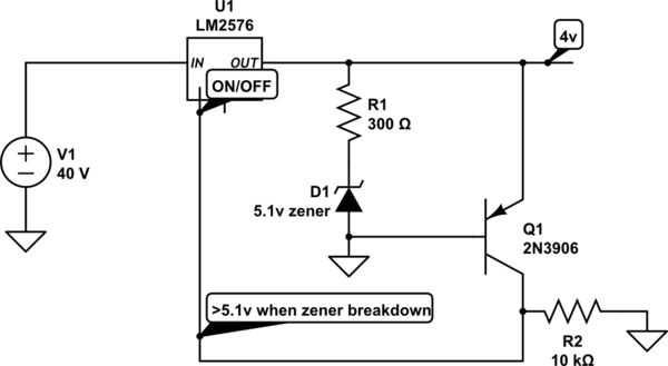
I'm trying to shut down an LM2576 regulator in the event that one of its adjusting resistors fails open. I'd like to use the ON/OFF pin on the regulator as this seemed as though it should be easy and cheap, and stops the current rather than having it dissipated as heat. The input is between 5 and 37v, and if this resistor fails, it sends that voltage all the way through to the rest of my circuit, exploding capacitors and killing the processor.

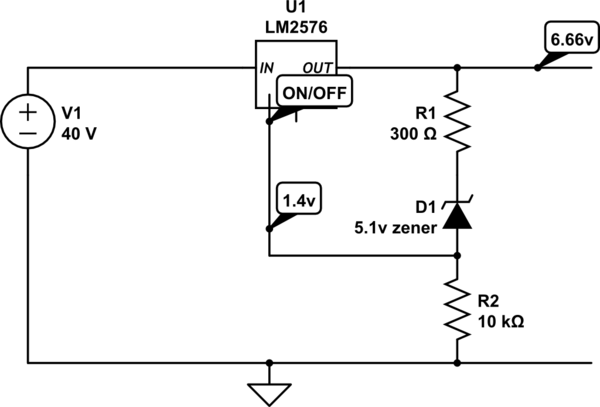
The ON/Off pin needs 1.4v to start shutting down the regulator, which i'm able to feed from the 5.1v zener as in the schematic below (I hope it's below, this is my first post, sorry if i've got it wrong!) But it needs around 5v for full shutdown, which is what I'd like. The schematic is simplified obviously, there are capacitors and whatnot in there as needed by the LM2576

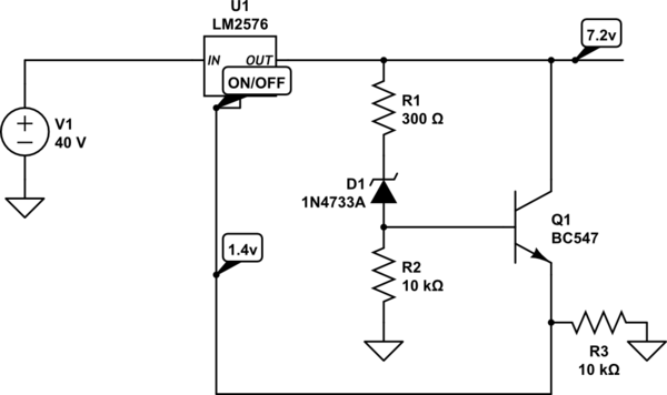
My problem is that by feeding it through the zener, it only limits the output to 6.7v, I assume because this is the voltage the zener needs to give the pin 1.4v. This is enough to stop things exploding, but not really to fully protect the circuit. If i give a direct 5v or 12v or whatever to the pin, it shuts it down completely. I've tried using the zener to feed a transistor, but this just ups the voltage to 7.2ish, and as the pin needs to be pulled high, i can't just use the transistor to go to GND.

I'm sure I'm missing something really obvious, but I can't see it! Can anyone help please?!
schematic

simulate this circuit – Schematic created using CircuitLab
schematic

simulate this circuit

\$\endgroup\$
2
  • 1
    \$\begingroup\$ Why do you expect that the resistors may fail? A resistor failing, especially a feedback resistor that shouldn't have much current through it, is very rare. \$\endgroup\$
    – Hearth
    Commented Jul 26, 2021 at 13:43
  • \$\begingroup\$ I don't really expect them to, I agree it would be really rare, but it's for use in a boat, and it's going to get banged around a lot. The high voltage could also work it's way over from a stray wire or something, I'd just like to give a shutdown if that happened. I don't really want capacitors exploding at sea. It gave me a bit of surprise yesterday! \$\endgroup\$
    – Marcus
    Commented Jul 26, 2021 at 13:53

3 Answers 3

2
\$\begingroup\$

If you use negative feedback to EN! With a threshold of 1.3V for OVP, it will oscillate from a over-voltage condition. You may want to use a latch for this function with POR and an indicator. Or some other autonomous retry method.

Make sure your step load response is stable with acceptable overshoot.

You might consider a current limiter on the input.

\$\endgroup\$
12
  • \$\begingroup\$ Thanks Tony, I'm not quite sure what you mean by a negative feedback to EN! But the idea of a latching POR has made me realise that I should probably just have another fuse of some sort triggered by a zener, as this situation means something needs to be reattached to the PCB. This means a much bigger zener that can handle the current though and I'm not sure it would all be fast enough to protect the caps and MCU. I suspect that the way i have it set up now is causing it to oscillate, but it sits there happily and the resettable fuse isn't triggered as there's hardly any current going through. \$\endgroup\$
    – Marcus
    Commented Jul 26, 2021 at 14:10
  • \$\begingroup\$ When EN! Goes above 1.3V output drops then EN! drops below 1.3 and output goes high .. this is a negative feedback relaxation oscillator if OV condition returns when enabled. \$\endgroup\$
    – D.A.S.
    Commented Jul 26, 2021 at 14:14
  • \$\begingroup\$ Thanks Tony, I believe this is the situation that I've arrived at so far. As the Zener provides the ON/OFF (Enable Input) pin with 1.4v, but only when the cathode of the zener has reached 6.66v, capping the PCB output at 6.66v, no doubt oscillating slightly above and below it. But really i need a way to increase that 1.4v in order to bring down the 6.66v to somewhere below 5. I can reduce the zener voltage to 4.7v, which will no doubt help (my circuit runs at 4v) But I think what you're suggesting is that I use a schmitt trigger or something in order to avoid the zener altogether? \$\endgroup\$
    – Marcus
    Commented Jul 26, 2021 at 15:00
  • \$\begingroup\$ Yes you can try all those but that won’t latch an OVP permanent failure . If it is an overshoot protection, then a better solution is needed. Test your regulator for overshoot to simulate a down step to sleep mode, then test with a cap failure (higher ESR), then figure out how to detect and report a fault before it occurs and shutdown has occured \$\endgroup\$
    – D.A.S.
    Commented Jul 26, 2021 at 15:18
  • \$\begingroup\$ Great Ok thanks Tony, I'll re-think it. Perhaps a permanent fusable link and a high current zener is the sensible way. \$\endgroup\$
    – Marcus
    Commented Jul 26, 2021 at 15:22
0
\$\begingroup\$

So, from what I understand from Tony's suggestion is this. I possibly just need to use a PNP transistor rather than NPN, as this will give me more voltage to the ON/OFF pin when it's triggered by the zener:

schematic

simulate this circuit – Schematic created using CircuitLab

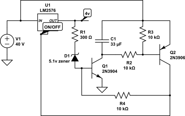
Hmm, drawing it out the way i understand it has made me realise that this will still just oscillate the output at 5.1v again and never actually turn the regulator off. So I think I might be looking in the wrong direction really. So, does anyone have any opinion on this latching version? Its getting a bit big, but I think I've got room:

schematic

simulate this circuit

If the output voltage rises above 5.1v, the zener triggers the NPN, pulling the PNP to GND, which in turn sends the unregulated voltage (up to 40v) to the ON/OFF pin and back to the NPN through the bottom resistor, turning off the regulator and keeping it off until the 40v is turned off. I've seen a few of these schematics, but sometimes they omit the cap and R2, and I can't really see any need for them. Transients from the unregulated supply might damage the transistors I suppose, but i can't see how they can trigger them accidentally. obviously they need to be rated for over 40v.

\$\endgroup\$
1
  • \$\begingroup\$ I was wrong , high gain positive feedback is what I meant with positive logic to disable rather than is high gain negative feedback for negative logic to disable. But in any case high gain is what you needed rather than unity gain and cap. memory rather than FF memory. \$\endgroup\$
    – D.A.S.
    Commented Aug 1, 2021 at 11:51
0
\$\begingroup\$

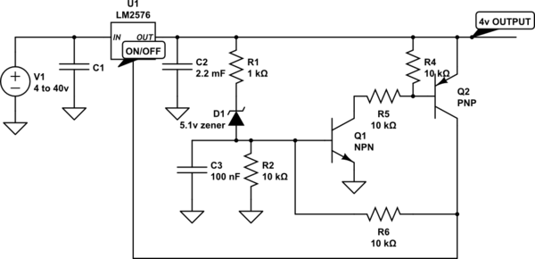
If anyone else is trying to do the same, this works:

schematic

simulate this circuit – Schematic created using CircuitLab
It needs the pull-down R2 to stop Q1 accidentally closing, and it needs C3 in order to reset. Otherwise the residual voltage left in the power supply capacitors C2 can hold it closed even when power is removed from the system, making it impossible to reset.

Once the latch has been sent (which it does at 5.3 V), it turns off the regulator, but that still outputs enough current at 2.4 V to keep the latched closed, and the ON/OFF pin high, and so it's possible to use the regulated output from the LM2576 to feed Q2 rather than the unregulated output which could be running at 40 V or whatever.

\$\endgroup\$

Your Answer

By clicking “Post Your Answer”, you agree to our terms of service and acknowledge you have read our privacy policy.

Not the answer you're looking for? Browse other questions tagged or ask your own question.