All this means is your power supply is unable to drive the current needed to suddenly absorb the excess power generated from a rising RPM due to a drop in load with back EMF acting as a generator.
When duty cycle is high and RPM is lower than no-load and RPM suddenly rises with drop in load, then no-load average voltage may be higher than driver average voltage. in this case as @Marco suggests , you need a voltage error amplifier to lower the PWM duty cycle thus loading the back EMF which causes the over-voltage.
Dynamic compensation must be determined according the duration of the disturbance.
Alternatively lower the impedance of your 48V supply so that it has an ESR of 1% of the Motor DCR so that this “load regulation error” of 4% does not occur. (Easier said than done without specs)
rev A
Controlling rate of change of load must not exceed ability to match rate of change and amount of current.
Achieving this low load regulation error is a matter of impedance ratios from source to load and rates of change controllability.
to solve this , first you must define all these variables with details; a spec, schematic and photos
source power, impedance, load inertial energy stored, power transfer, max V , t rise max.
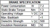
Rev B , new specs
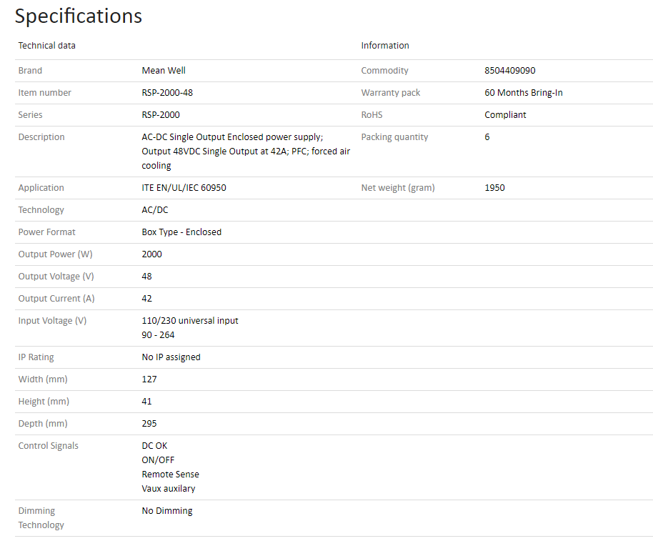
Load Regulation error 0.5% of 48V = 240mV (good). And 0.5% of 48V/42A= ~ 5.7 mOhms for “push” not necessarily “pull”.
Inductive flyback (high from motor dI/dt).
Load Caps on supply 4.7mF x6 unknown ESR … worst case net for 2V rise/12A drop = 1/6 Ohm or ESRC= 4.7 ms but rise time of the current pulse determines frequency BW and impedance of pulse. ESR= D.F. |Xc| where |Xc|= T(rise time)/ 2pi 0.35 C)
How this affects stability of supply is also important with power on surge currents and phase margin.
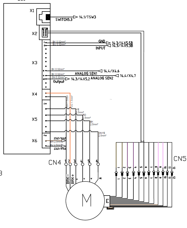
network impedance of the load is complex ,so include wiring type, length and Cap datasheet link e.g. and if possible rise time of pulse with coax and AC coupled 50 load to DSO.
finally Meanwell OVP is programmable to 115 % = 55V
- This ought to be selected and use caps with higher than 63V for better quality and lower ESR.
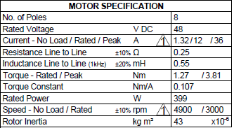
Motor L = 0.55 mH. DCR = 0.25 Ohms.
Thus T=L/DCR= 220 ms +/-30%.
I load = 12A rated thus I *DCR = 4V so flyback voltage can be attenuated to 1V or 25% of this with cap ESR of 1/5 of 0.25 ohms or 50 mOhms with a C value C=T/DCR = 220 ms/50 mOhms = 4.4 Farads ! This can only be accomplished with SuperCaps or double electric layer caps or a battery.
This suggests your best solution is a 48V battery with low ESR and a 12A battery charger /regulator for float voltage of 48V using an ESC motor controller rated for >= 1Hp Hmm
Q at resonance is \$Q=R\sqrt{\dfrac{L}{C}}\$. Which for motor with supply caps L = 0.55mH,DCR = 0.25 Ohm C= 4.7mF * 6 , ESR = ?,
Or \$\dfrac{1}{Q} = \dfrac{1}{Q_L}+\dfrac{1}{Q_C}\$
Anyone see anything wrong with my calculations OR wish to simplfy or correct?? Go ahead.


