2
\$\begingroup\$

I want to use the thermistor inside of a battery pack on the BQ25887 and on a GPIO pin on a microcontroller so that both the microcontroller and the charging IC can monitor the battery voltage. For reference, I'm using the ATMega32U4 with a 5 V regulator.

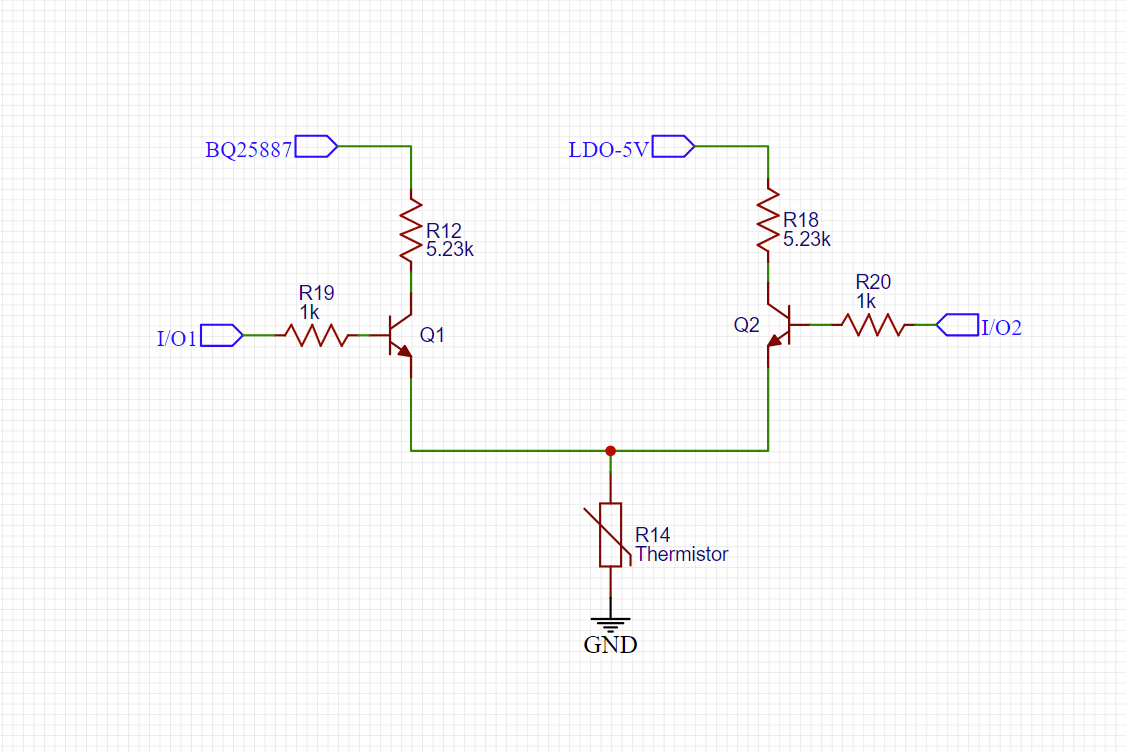
If the charging IC is powered, then I want the thermistor to be used on the BQ25887. If it is not, then I want the thermistor to be used on the microcontroller. I'm trying to think of a way I can use two switches to switch between the charging IC and the MCU. I can't use an optocoupler since that takes up too much space on my PCB. Here is what I have now, and here are the questions that I have.

  • Can NPN transistors be used as high side switches like this?
  • If no current is flowing through the base, will the transistors truly be open?

My concern is current backfeeding into either the LDO 5 V line or the BQ25887.

enter image description here

\$\endgroup\$

3 Answers 3

2
\$\begingroup\$

It depends what voltage you want to deliver to the thermistor.

Remember you need to drive the base of the BJT about 0.6 or 0.7 V above the emitter. So if you only want to power the thermistor with 2.5 or 3.3 V, then you have no problem.

But if you want to deliver the full 5 V to the thermistor, then you need to find a way to provide 5.6 V or so to the base. This can be done, for example using a boost converter circuit, even a very crude one.

But the more usual solution, when keeping the circuit simple is a priority, is to just use a PNP BJT instead of NPN, and invert the control logic.

\$\endgroup\$
2
  • \$\begingroup\$ Wouldn't the thermistor always have a voltage lower then 5V across it in the circuit shown? \$\endgroup\$
    – Jay
    Commented Aug 22, 2021 at 16:24
  • \$\begingroup\$ @Jay, it depends what is attached to the I/O1 and I/O2 pins. If you can apply, for example, 8 V there, then you can get more than 5 V at the thermistor (but then power would be coming from the I/01 or I/O2 pin, not from the BQ25887 or LDO-5V inputs). \$\endgroup\$
    – The Photon
    Commented Aug 22, 2021 at 17:45
2
\$\begingroup\$

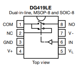
A better approach might be to use an analog switch such as the DG419.

enter image description here

On resistance is less than 37Ω with a 5V supply, and leakage is nA.

\$\endgroup\$
2
\$\begingroup\$

You could change the circuit a bit and use a Logic Level P-Channel MOSFET where the source connects to voltage source such as LDO-5, the base connection becomes the gate and your resistor connects to the drain and your load. Look for something complementary to the 2N7000, the BSS84 should work fine and is available. Check the datasheet for the ones you purchase, some have a bad datasheet such as: "https://www.mouser.com/datasheet/lrg/395/BSS84_A2007-2064290.jpg" It states low side switching, it should state high side switching. I found no VGS curves for them.

\$\endgroup\$

Your Answer

By clicking “Post Your Answer”, you agree to our terms of service and acknowledge you have read our privacy policy.

Not the answer you're looking for? Browse other questions tagged or ask your own question.