I have a digital voltmeter, it has 3 pins, 2 for power and 1 for measurements, if I connect its ground to the circuit's ground, I can measure any 1 point of the circuit, but I can't measure between any 2 points in the circuit.
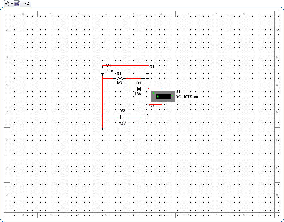
This is part of a variable power supply design, I want to measure the output voltage without bringing in the voltage drop by the Rds(on) of the N-MOS on the ground side (Yes, I'm going to output high current with this), it is probably negligible for the most part, but I want the volt shown to be as accurate as possible. And I can't just connect the ground of the voltmeter to the drain of the N-MOS because this N-MOS might be turned off for overcurrent protection or something (if I do decide to put it in for the final design) in which case the voltmeter will also turn off. I have no idea how to measure the output voltage with only 1 measure pin, any help?
Also I have no idea if the N-MOS is a good idea, I just want to prevent any current flowing in from the output side to blow things up when the power supply is unpowered, and this can probably prevent any current from flowing in from the output in any direction, any feedback on this is also appreciated.
Some more information regarding this, the 30V in the picture shown is actually provided by a power BJT that is in Darlington pair with a smaller BJT controlled by an Op-amp, and everything is powered by transformer through bridge rectifier and a big capacitor which gives 32V, I can get almost 30V max on the output and this is probably because of Vce(sat) on the BJT.
When unpowered and without the N-MOS on the output, if someone decided to put voltage on the output side such that the ground is positive, the bridge rectifier shorts everything (probably, or maybe the Op-amp shorts itself and blows up, I wouldn't know) except the BJT because it is in series, but until here I don't know what happens next, the base of the BJT is connected to the Op-amp which is shorted, so I don't know whether the BJT is on or off, if it is off, then the whole thing is open circuit, if it is on, then the BJT and P-MOS will probably just heat up.
I don't know which will happen because maybe the Op-amp is shorted and is positive, that means the base of the BJT is positive as well which turns it on. Or the path from the Op-amp to the base will have such high resistance that the current doesn't turn the BJT on, but then again darlington pair has high gain so I just don't know.
But I don't want to take any risk thus the N-MOS to prevent any power coming in from the output side in the first place, is this a good or bad idea? Because I didn't google for this idea, it is something I added myself, and is probably not common in designs.
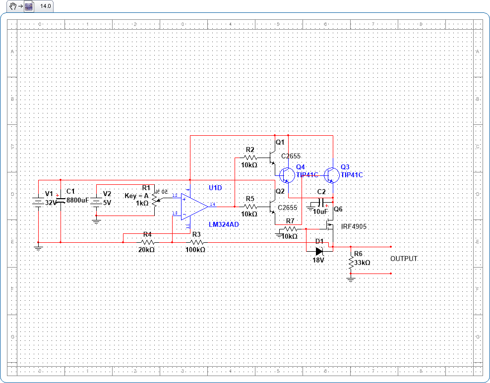
This is the current working schematic that I have built and ready to solder, I have gone through rigorous testing and blew up more than 50 C2655 to arrive at this design. There are definitely some stuff to comment here like the two TIP41C, yes I have read it and all, thermal runaway and all that stuff, but still, 2 transistors still carry more current than 1, and currently I only have these two power transistors, I'm making this power supply all because my previously bought, cheap ones are broken and these are all salvaged parts (transformer and TIP41C only).
There are big separate heatsinks on both TIP41C and I measured how each of them carry currents, they carry current almost equally I suppose (Both heats up, both measured numbers that add up, I even tested with 1 TIP41C, and with 2 TIP41C, 2 TIP41C gave more current so it works). If it works then it's a win for me, I tested short circuit, nothing blows up, but do get very hot after awhile, short circuit with multimeter gives me 4A and drops to 6V.
Also just imagine the 32V as 4 diodes and a 32Vp AC please. And if I were to use N-MOS, I will probably connect the 20k Ohm resistor to the drain of the N-MOS instead of ground.
There are more things to add, like an Arduino which I will use to digitally output precise voltage with some buttons (a relay will be used to switch between digital PWM input or analog potentiometer input), the Arduino will also monitor short circuit and temperature and whatever because I'm too lazy to implement these with analog circuit (I can even do cool things like outputting waveforms so why not just use an Arduino, it's a programmable power supply!).
Basically most of this circuit is tested, the final stage of the design is only the N-MOS part, which is why I only put the schematic of the output side.
Comment on existing circuit if only you feel like it will explode and burn my whole house down if I use it, otherwise I really only need suggestion on the N-MOS (basically output protection part).


 .
.