16
\$\begingroup\$

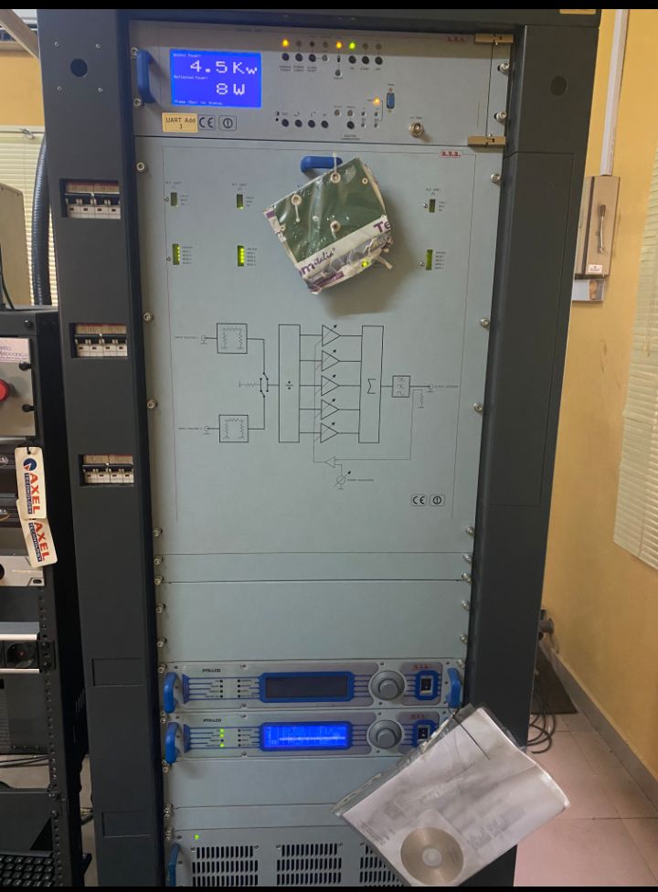
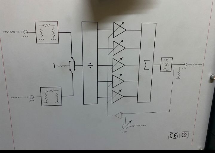
This is the circuit diagram on the transmitter at a local FM radio station I clean at (I'm a janitor,) but I'm also studying electrical engineering. I'm puzzled by the circuit diagram on the transmitter. What do the symbols on the diagram mean and how can it be used to explain how a transmitter works?

enter image description here

\$\endgroup\$
1
  • 11
    \$\begingroup\$ That's not a circuit diagram. It's more of a functional block diagram. \$\endgroup\$
    – brhans
    Commented Sep 28, 2021 at 17:44

3 Answers 3

14
\$\begingroup\$

It's not a circuit diagram, but a block diagram, which means it can't be used to understand the transmitter at the component level.

However it can be used to aid a first level diagnosis of problems, and which circuit board or black box to replace when something fails.

Reading it from left to right, we have:

  • Two input sockets, labelled "Input exciter 1,2". An exciter is actually a complete low power transmitter : probably 8 Watts judging by the top display. And the exciters are probably the blue handled boxes below, of which only one is currently in use. This isn't unusual; transmitters are designed for redundancy; if one exciter fails, the other can be started immediately to keep you on air (and this may even be automatic)
  • Each exciter feeds a "pi network" of three resistors, into a changeover switch. This provides impedance matching. You may not have got there yet, but radio signals tend to "bounce" off the wrong impedance, and either open or short circuits can reflect signal back into a transmitter, and overheat it. The pi network may also provide attenuation between the exciter and the later stages.
  • The changeover switch connects one exciter into the power amplifier, and the other one into a resistor called a "dummy load" to absorb the power frrom the other one. Again, this changeover is probably automatic and its status is probably shown by the LEDs above.
  • The first stage of the power amp is a signal splitter (or divider, which probably explains the odd symbol on it!) to feed the same signal to five actual amplifier modules. In other transmitters there may be signals from different studios carrying different channels, but apparently not here.
  • Each amplifier has its gain controlled by the "power modulation" control, combined with a signal fed back from the antenna (so that if something goes wrong at the antenna, the reflected power is kept under control). As this transmitter is apparently producing 4.5 kW, presumably each amplifier is contributing 900W. Some transmitters must adjust their power at different times of day, to prevent signals travelling too far at night.
  • The five amplifier outputs are combined in a combiner (with the sigma symbol) which has to ensure that if one amplifier fails, the others don't dump their output into it!
  • Then a low pass filter (note the middle and top waves are crossed out) to eliminate distortion products from the amps, which would transmit on somebody else's channel)
  • and finally the antenna connection.

So it is not a complete transmitter, but a power output stage. And it is likely to be a custom assembly from standard components for a specific power level from a specific station, apparently with just one channel.

You may have noticed that most equipment doesn't have a block diagram on the lid : here, because transmitter installations are often custom built, the block diagram illustrates the specific configuration to help a transmitter engineer who may be called in to service or repair it. This ties in with the array of LEDs above, which are likely to indicate the status of each block, to pinpoint the fault fast.

\$\endgroup\$
8
\$\begingroup\$

As noted, this is not a "schematic", its more of a functional block diagram.

  • The triangles are power amplifiers. The arrow means they are adjustable.

  • The Sigma symbol means the amplifiers outputs are being summed (added) together.

  • The box with the 3 waves (after the sigma box) is a filter

  • The division symbol is indicating that it is dividing the input among the amplifiers

  • The lines with dots to the left of the divider is a DPDT switch.

  • On the far right is a resistor symbol that is a feedback element which goes into a negative feedback amplifier(the little circle on the triangle at the bottom indicates inversion), which then controls the gain on the power amplifiers.

\$\endgroup\$
3
  • 1
    \$\begingroup\$ The bit between the filter and output connector is a directional coupler which monitors the output power. The symbols on the bottom forms a feedback network which adjusts output power and keeps the output power leveled (consistent). \$\endgroup\$
    – qrk
    Commented Sep 28, 2021 at 18:11
  • \$\begingroup\$ @qrk thanks, I got busy with a meeting for a bit. Added the feedback point. \$\endgroup\$
    – Aaron
    Commented Sep 28, 2021 at 19:04
  • \$\begingroup\$ @CGCampbell Usually the word "double" is used, but yes. Double Pole, Double Throw. \$\endgroup\$
    – Aaron
    Commented Sep 29, 2021 at 16:44
5
\$\begingroup\$

I honor your curiosity!

The FM transmitter components are contained in the cabinet, but the diagram only represents the final amplifier stage. The FM signal actually originates in an "exciter" and I believe those are the small rack items at the bottom. There are actually two of these, probably for reliability reasons. They produce only low power, I'd guess 8 watts based on that label at the top.

The block diagram is an amplifier that boosts the signal power up to several thousand watts (4.5 kilowatts according to that label again). The block diagram begins with a pair of switches to select which of the two exciters is in use. The other one is routed to a resistor that serves as a "dummy load".

The large vertical block with the "division" symbol is a divider that splits the exciter power into 5 different amplifier circuits, then the "summing" (greek sigma) box recombines them. Why? I'd guess so each amplifier only has to produce about 1 kW, and that's easier and cheaper than building a single 5 kW amplifier. These amplifiers have variable gain (the slanted arrows) so the station can change the power level.

After the amplifier signals have been recombined, there's a filter. That's the box with the sine wave pictures, some crossed out and one that's not. This keeps unwanted harmonics from getting to the antenna.

Finally, there's a coupler that picks up a bit of the output signal, measures it, and sends it back to the power regulator. This is compared with a "desired power" setting, and if they don't match, the amplifier gains will be automatically adjusted.

If you find electronics interesting and want to tinker with it, there's not much opportunity at a broadcasting station. Look into amateur radio. Licenses are easy to get, and equipment is low in cost. Best of luck!
\$\endgroup\$

Your Answer

By clicking “Post Your Answer”, you agree to our terms of service and acknowledge you have read our privacy policy.

Not the answer you're looking for? Browse other questions tagged or ask your own question.