0
\$\begingroup\$

I'm currently working to quiet down the emissions from a stepper motor drive circuit.

The motor drive frequency is 22kHz, and there is significant 60MHz noise that comes ONLY from the 36V side as motors are driven or simply held in position. So far I've tried adding 1 Ohm gate resistors which caused some terrible shoot-through, and notably still left a big "hump" around 60MHz even though it reduced the 2.2MHz-spaced harmonic "spikes". I'm trying to approach the problem with an LC circuit at the output.
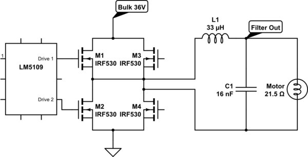
schematic

simulate this circuit – Schematic created using CircuitLab

This old app note seems to do the best job of walking through calculations and the general approach. I also found this question which is really in-line with what I want to do.

Unfortunately both sources suggest an inductor that's ~1/10 the motor's own inductance (about 160uH in this case), and the biggest I had laying around was 33uH. I used a 14pF cap for a cutoff frequency around around 220kHz, and was rather disappointed to see the spectrum change (fewer spikes) but still stay over the limit at 60MHz. I would have thought a cutoff frequency that far away from the problem area would have more of an impact.

This all leads into my question - how does the inductor factor into reducing the EMI from a motor? Simply by smoothing out the ripple current in the motor, and my inductor couldn't smooth it out enough? Are there more resources I can use to understand this better?

\$\endgroup\$
7
  • \$\begingroup\$ Link motor specs and load current limits along with cable type and scope 10:1 probe gnd length SVP, for a better answer! \$\endgroup\$
    – D.A.S.
    Commented Dec 8, 2021 at 2:43
  • 1
    \$\begingroup\$ I had a similar problem with a low side mosfet switch. Due to the inductance of the source wiring, i’d get bursts of around 70MHz when it turned on. So have a close look at your current paths and view every wire as an inductor. An inch or so is all that is needed. Make yourself a little sniffer loop as a probe for your scope and go sniffing. The results might surprise you. Having a spectrum analyser makes it easier. \$\endgroup\$
    – Kartman
    Commented Dec 8, 2021 at 2:56
  • \$\begingroup\$ @Kartman yes this is being done with a spectrum analyzer. What specifically did you change on your low side FET? This isn't a board I laid out, so there's a lot I would do differently... \$\endgroup\$
    – Drewster
    Commented Dec 8, 2021 at 3:02
  • \$\begingroup\$ The driver source impedance will have Coss capacitance with low RdsOn but R rises quickly when the driver goes into CC mode which performs better. You need to specify the driver and settings, otherwise your question gets lost in the "noise". Everything needs an impedance spec. to model it from DCM to CCM to Voltage source and fix it from diff LPF to CM choke to cable type and snubber type. Got it? The diff chokes need to be more like 1% of motor inductance and RdsOn same~ 1% of motor DCR. My guess DCR is 0.5 ohm \$\endgroup\$
    – D.A.S.
    Commented Dec 8, 2021 at 3:51
  • \$\begingroup\$ @Drewster, i fixed up the ‘inductor’ on the source - shorter and fatter tracks. If you suspect the pcb, then modify it by adding wires or capacitors across the suspect tracks. Having no gate stopper resistor would make the issue worse. If you had problems when adding a 1Ohm gate stopper, then that suggests you have other problems. 1Ohm should add a few nanoseconds to the switching time of the mosfet. If the circuit is that sensitive, then there’s other issues methinks. Substitute a resistive load instead of the motor and see if the observed issues change. \$\endgroup\$
    – Kartman
    Commented Dec 8, 2021 at 5:32

3 Answers 3

1
\$\begingroup\$

When the rise time < 1/2 the cable prop delay if 5 to 6ns/m and single and differential impedances give poor CMRR, it's time to consider lower impedance dual shielded STP cables and A CM choke with high Z xx to xxx ohms but withstands rated current easily.

Be sure you are not measuring probe resonant frequency with gnd lead and probe gnd ESL and coax C pF/m

The full bridge drivers also need very low ESR bulk caps.

\$\endgroup\$
5
  • \$\begingroup\$ The noise doesn't appear on the scope until motors begin to drive - the regulators, etc. on the board are measurable but nothing in comparison to the noise once the motor is being driven. Does that rule out the resonant frequency of the probe? I'll add some specs and screenshots tomorrow if my machine lets me. Might try a Tantalum or something on the bridge for grins... \$\endgroup\$
    – Drewster
    Commented Dec 8, 2021 at 3:01
  • \$\begingroup\$ That depends if you are using Dif probes or two singles in A-B and the idle mode is CC (controlled current limit , as most CNC shields and stepper drivers might be. gotta have more details ! \$\endgroup\$
    – D.A.S.
    Commented Dec 8, 2021 at 3:57
  • \$\begingroup\$ The noise is being measured with an E-field probe and spectrum analyzer - there aren't any probes attached to the PCB. \$\endgroup\$
    – Drewster
    Commented Dec 8, 2021 at 14:34
  • \$\begingroup\$ That's good. RLC filters attenuate by a spectral attenuation but can also amplify with resonances of unknown impedances. Which is why I requested that information by links of all end to end parts. 1 Ohm Rgate is not a major problem but 1 nH per mm can be problem in the path. Every parasitic capacitance and inductance including the motor where you only gave R and not L or C by measurement adds a power to the scattering parameters for return loss and forward and reverse transfer function. With very low ESR bridges, many things can go wrong when the cable impedance. This is why CC works better \$\endgroup\$
    – D.A.S.
    Commented Dec 9, 2021 at 0:04
  • \$\begingroup\$ With CC mode the drivers are high impedance on idle and then then snubbers and RLC LPF's can be designed to dampen the response and radiation noise. CM chokes are essential and are used on all large stepper CNC pick and place and PCB assembly servos. So please add more links to end-to-end components devices, incl. cable and lengths \$\endgroup\$
    – D.A.S.
    Commented Dec 9, 2021 at 0:06
0
\$\begingroup\$

If the noise is traveling through the wires, then, to answer your question, an inductor does work by smoothing out the ripple.

If your filtering circuits are not doing what you expect, there may be another path of transmission.

For example, the motor (or some other circuit) may be radiating the noise, and your wiring (especially if it is long: let's say a meter or more) might be picking up the noise.

If that is the case, try shielding the wires. Good luck!

\$\endgroup\$
1
  • \$\begingroup\$ Thank you! This setup is pretty isolated but I'll probe around \$\endgroup\$
    – Drewster
    Commented Dec 8, 2021 at 3:07
-2
\$\begingroup\$

you need to filter all the driven motor wires. in the drawing you have only filtered the top wire. the bottom wire can still act as an antenna.

grounding the capacitors instead of tying them to the opposite motor lead will hep prevent the cable from acting as an electric field antenna.

\$\endgroup\$

Your Answer

By clicking “Post Your Answer”, you agree to our terms of service and acknowledge you have read our privacy policy.

Not the answer you're looking for? Browse other questions tagged or ask your own question.