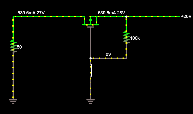
My goal is to add two toggle switches to high power DC lines so that I can break the circuit and stop power from being delivered to my load. This load will be using 28V, ~27A. I have an two channel 2kW isolated PSU (+28V, +28V, COM, COM) that is more than capable of supplying this kind of power. I have found toggle switches that are rated appropriately, however, they use screw terminals which in my case is undesirable (lots of wires).
I would like the switches to be mounted to a PCB with PC pin terminations. For this, I am thinking of using a Power FET to switch the power on/off. The lower rated PC Pin toggle switch will be attached to the Gate of the FET.
I have created this simulation in Falstad using a high-side P-MOSFET and a resistor to simulate my load. I would need to of these circuits in total for each switch.
There are two concerns that immediately come to mind.
- Assuming the components used are appropriately rated, how will this circuit perform at high current? Are there missing components that are required when operating at a high current, that otherwise would not be needed?
- Will having a floating ground cause this circuit to fail due to the gate being tied to ground? I have an LDO that spits out 15V available. Could I use this at the gate if it meets the Vgs difference requirement for the FET?
Any thoughts or ideas are appreciated. There is likely an easier way of achieving this system with PC pin toggle switches that I am not aware of.

