1
\$\begingroup\$

I'm building a DC-DC step-up (boost) converter using TL494. The schematic is attached

  • Input voltage: 9V
  • The resistive divider at the output sets the output voltage to about 14V
  • Desired output current: 3-4A
  • The inductor is wound on a ferrite powder core, a cheap LCR meter measures it as about 500uH
  • C1, R1, R2 set the oscillation frequency to 200kHz
  • C2 and R3 provide soft start functionality (strangely, the converter doesn't start properly without it - it draws a lot of current and Q1 starts smoking)
  • R5 and R6 are to reduce error amplifier gain (https://www.ti.com/lit/an/slva001e/slva001e.pdf, section 5.2.2), but they seem to be ineffective when fixing my problem described below

The circuit can provide a few tens of mA without a problem, but when I connect a 30 Ohm load, it starts making audible noise (probably a mix of frequencies in the 100s of Hz range, not buzzing) and the voltage jumps to 15.5-16V.

I tried a bunch of different measures:

  • doubling the frequency (100kHz to 200kHz) and the inductance (250uH to 500uH) helped to reduce the increase in voltage from 17.4V to 16V
  • Adding 4.7nF and 100nF capacitors to the output divider (across R8) and across pins 2 and 3 of TL494 (values and placements tried separately) changed almost nothing
  • Adding a 1uF electrolytic capacitor across R8 makes the output voltage go to 15V without load

Is there anything else I could try? I couldn't find any generic pieces of advice on what to do in such a case, so any help would be appreciated.

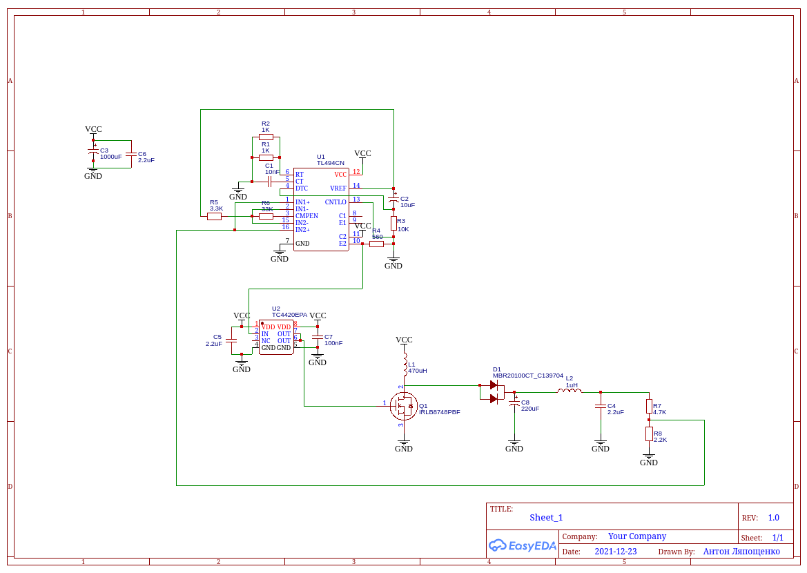
Schematic

\$\endgroup\$
6
  • \$\begingroup\$ What's the saturation current of your inductor? \$\endgroup\$
    – John D
    Commented Dec 23, 2021 at 19:24
  • \$\begingroup\$ I don't know it. The inductor is wound on an iron powder ring from an ATX PC power supply. Is there an easy way to find it out? Or, alternatively, I can try reducing the number of turns or sticking two such cores together - will any of this work? \$\endgroup\$
    – Anton
    Commented Dec 23, 2021 at 19:34
  • \$\begingroup\$ The reason you need the soft-start to make it work may be because otherwise start-up saturates your inductor. (Maybe inrush through the diode.) You can measure Isat by putting a current probe on the inductor and using a current-limited lab supply to apply a voltage across it to see where it becomes non-linear. Andy's answer also points out that you need to take stability and loop compensation into account. The extra phase shift from your post-filter isn't helping at all. \$\endgroup\$
    – John D
    Commented Dec 23, 2021 at 19:43
  • 1
    \$\begingroup\$ Have you worked out how much phase margin you (don't) have? \$\endgroup\$ Commented Dec 23, 2021 at 19:56
  • \$\begingroup\$ I don't have enough equipment to test Isat, but it seems like you're right about the soft-start - I added it because I thought that the inrush (LTSpice showed >40A) saturated my inductor. But now I seem to be running into saturation with higher loads - so am I correct in thinking that I can reduce the number of turns (500uH seems too big for 200kHz according to ti.com/lit/an/slva372c/slva372c.pdf?) to increase the saturation current? \$\endgroup\$
    – Anton
    Commented Dec 23, 2021 at 21:05

1 Answer 1

2
\$\begingroup\$

It’s fundamentally wrong to have your feedback after the LC ripple remover. Move your feedback resistor divider to before that added LC filter.

There may be other problems but this is glaringly obvious because it will shift the phase angle of the fed back signal beyond the point of loop stability for a simple boost converter like this.

I estimate that you will have a loop stability problem somewhere a little under 100 kHz (maybe 90 kHz) given the values you have shown in the diagram and the possible series resistance of the 1 μH second inductor. About 0.2 Ω could be a problem and, when added to the extra phase shift at lower frequencies due to the 30 Ω load, it's going to sing and cause problems.

\$\endgroup\$
7
  • \$\begingroup\$ I wasn't aware of the fact that my divider placement is incorrrect - thanks so much for pointing it out. Do I understand correctly that I need to compensate pin 3 with a capacitor in addition to R5 and R6, as well as use values closer to 510 Ohms and 51K given in the TI note I linked? If so, could you please suggest a value for the capacitor? \$\endgroup\$
    – Anton
    Commented Dec 23, 2021 at 21:12
  • \$\begingroup\$ Compensation is normally needed without the extra LC filter. I suggest you move the divider. \$\endgroup\$
    – Andy aka
    Commented Dec 23, 2021 at 21:55
  • \$\begingroup\$ Great, thanks again for the tips. I forgot to mention it, but moving the divider worked just fine \$\endgroup\$
    – Anton
    Commented Dec 24, 2021 at 7:23
  • \$\begingroup\$ That's great news. \$\endgroup\$
    – Andy aka
    Commented Dec 24, 2021 at 8:01
  • \$\begingroup\$ Side note: I found out that R5 and R6 are actually necessary. If I remove them and connect pins 2 & 15 directly to Vref, the same behavior happens as if the divider was after the LC filter. Although with R5 and R6 the output voltage drops slightly under load because pin 3 voltage decreases under load, and R5 and R6 act like a voltage divider. So, increasing their ratio is the way to go. \$\endgroup\$
    – Anton
    Commented Dec 24, 2021 at 14:14

Your Answer

By clicking “Post Your Answer”, you agree to our terms of service and acknowledge you have read our privacy policy.

Not the answer you're looking for? Browse other questions tagged or ask your own question.