3
\$\begingroup\$

I was tasked to integrate a 48V tool (a brush, so basically a DC motor + some control electronics) on our 24V sub-sea robot for a short demonstration. We aim for depths of 100m (10 bar).

The brush requires 48V, and is driven at 1A (with potentially very short spikes at the begging of each PWM cycle).

The supply is 24V, with a 3A slow blow fuse.

So in theory, no big deal: I just need a boost converter with efficiency >67%.

The tricky part is that I have to insert this converter into the cable. A pressure resistant bottle to include an of the shelf converter would be a solution, excepted that it's quite expensive for a one-off project, and lead times are quite long.

So I would like a circuit that can just be molded into the cable. We quite often connect cables this way (joining 2 cables then molding the junction in epoxy, sometimes adding a small PCB with no pressure sensible components).

The problem is, I couldn't find any "serious" boost converter without any sealed component (likely to imprison some air, and therefore likely to implode under pressure). The only boost converters without sealed components I could find is amazon crap like this one (for this one, it seems they use 50V capacitors for 48V output, not good sign), and even then, I would need to replace the potentiometers by resistors to avoid them imploding.

This article also mentions that aluminum electrolytic capacitors are not well suited for high pressure (not sure if for 10 bar it's still OK or not).

Excepted using a pressure resistant bottle, and keeping looking for a decent off the shelf PCB without sealed components, do you seen any other solution?

One solution I'm starting to think about would be making my own PCB. Knowing that I have regulated 24V input, I can either go for a boost converter, or to some form of voltage doubler, whichever is simpler. Is there a topology you could advise that don't need sealed components, and if possible avoids electrolytic capacitors?

Constraints:

  • input: 24V (regulated), fused at 3A slow blow
  • output voltage: 44 to 50V
  • ripple: no real limitation, peak voltage should be <=52V, min voltage >36V
  • efficiency: I don't care as long as I'm within the supply limits (so >67%)
  • all components must resist at at least 10 bar (so no sealed components excepted if filled with epoxy or similar, electrolitic capacitors probably to avoid excepted if someone has experience enough to know they will be fine at 10 bars)

PS: in case you see an easier solution, I also have an unregulated DC voltage in the 250-340V range).

\$\endgroup\$
2
  • 1
    \$\begingroup\$ I've had tantalum electrolytics running without trouble at 100-120m depth for a few days, and they survived multiple cycles of this (typically with intervals of a few months between). \$\endgroup\$
    – brhans
    Commented Jun 5 at 17:12
  • 2
    \$\begingroup\$ A 24 V to 48 V boost with ceramic caps isn't difficult, though if it's potted the thermals might need consideration. Other than that, there should be lots of inductor choices that would be fine at depth. TI's Webench tool or equivalents from ADI or other vendors should be able to get you started. \$\endgroup\$
    – John D
    Commented Jun 5 at 17:29

1 Answer 1

5
\$\begingroup\$

True, aluminum electrolytic capacitors can't be pressurized according to the tests I have performed. 10 bars is about 150 psi. The capacitor housing will deform and seals probably broken.

An option is to pot the power supply in a hard-cast epoxy. Ideally, you want to pull a vacuum, but the electrolytic capacitors can't handle this. Thus, to get most of the air out, degas the epoxy before pouring, warm the assembly and epoxy to reduce viscosity, and put the assembly on a shake table to encourage the entrapped air to the surface. Since you're only going to 10 bar, some entrapped air can be tolerated.
Be sure to attach cabling to the power supply before potting.

The cabling and potted power supply can then be potted in polyurethane or Silastic.

I generally don't like potting aluminum electrolytic capacitors in a hard cast as they can outgas and potentially explode. Our production has only seen electrolytic capacitors vent twice on one of our products (the pressure housing for the capacitors has a relief valve). While exploding capacitors is rare, it is something to be cognizant of, especially when using cheap no-name power supplies with questionable electrolytic capacitors. To be on the safe side, use a reputable brand power supply.

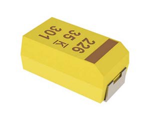
If you make your own power supply, I have found that molded polymer aluminum electrolytic and molded polymer tantalum capacitors survive 600 bars of pressure. Be sure you don't exceed the ripple current of the capacitor.

enter image description here
Molded epoxy polymer capacitor, image from a Kemet data sheet.

If you have access to a machine shop, you can probably make a housing out of 6066-T6 aluminum cheaper than sourcing epoxy and polyurethane. You can make a rectangular pressure housing since the pressure is fairly low. Design for 20 bars to give a 2x safety factor.

\$\endgroup\$

Your Answer

By clicking “Post Your Answer”, you agree to our terms of service and acknowledge you have read our privacy policy.

Not the answer you're looking for? Browse other questions tagged or ask your own question.