2
\$\begingroup\$

For a project I'm using the SIM7020 Narrowband-IoT (NB-IoT) module to send data to the cloud. The SIM7020 is controlled by an Arduino Pro Micro (ATmega32U4).

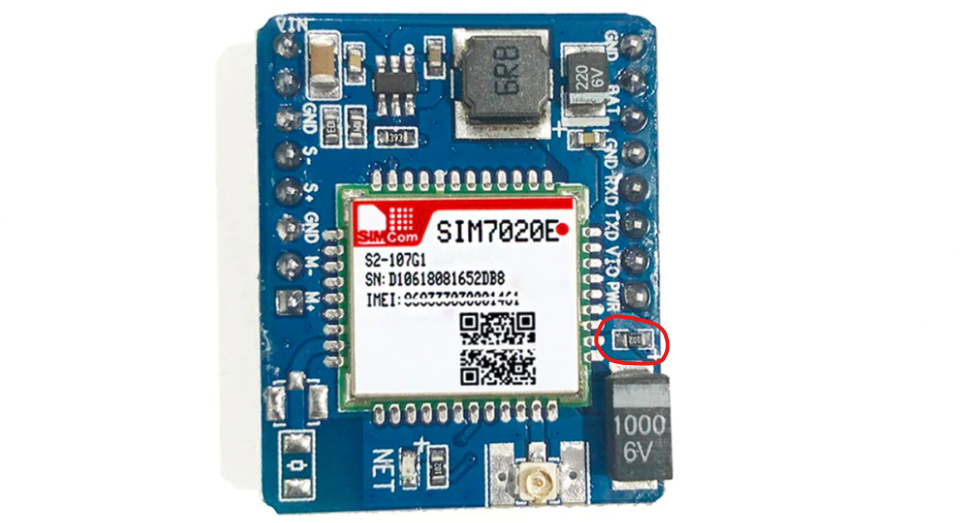
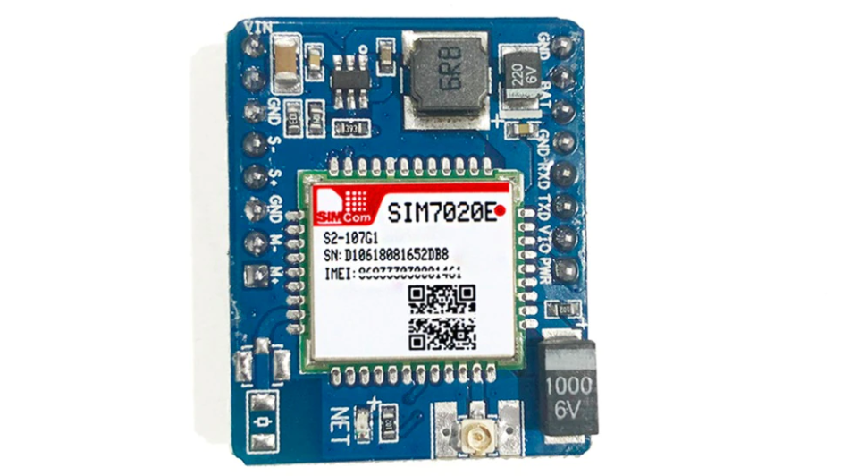
Identical SIM7020 module

Because the sensor is running on a battery, I want to have as low a current consumption as possible. I've already got the ATmega32U4 down to 35 µA, but I cannot get the SIM7020 module lower than ~7.5 mA even though the hardware datasheet states the typical usage in power saving mode (PSM) is 3.4 µA.

After sending a message with the module it enters the PSM mode (page 16-17, chapter 6.2.5 low power mode application.) This works fine. The Arduino receives +CPSMSTATUS: "ENTER PSM" and the status light on the module stays off. Then the current draw of the module drops to ~7.5 mA.

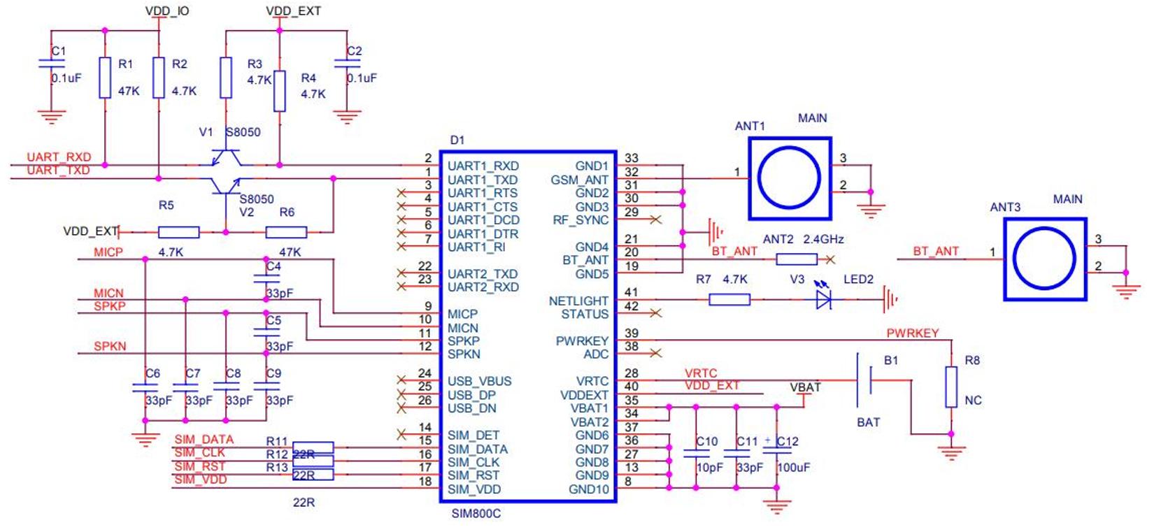
Schematic of the SIM7020 module chip:

Schematic of the SIM7020 module chip

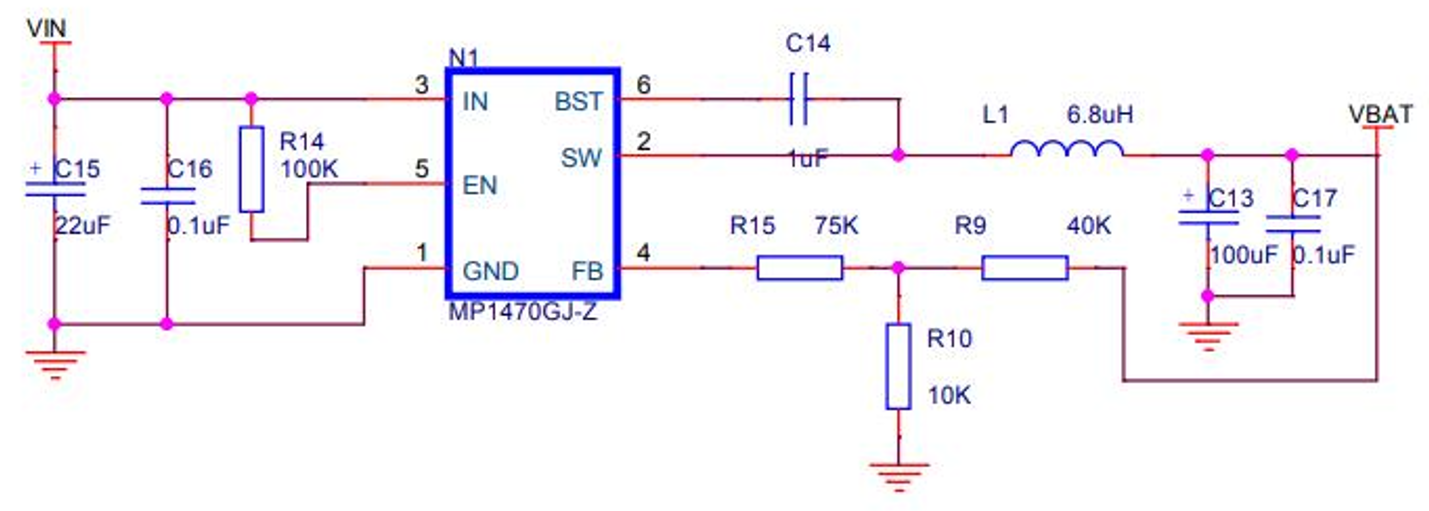
Schematic of the SIM7020 module power supply:

Schematic of the SIM7020 module power supply

I'm powering the module through the VBAT/BAT pin (with 3.3 V) and I also removed the MP1470. Also fully powering off the module (with AT commands AT+CPOWD or PWR pin) doesn't change the current significantly (still stays around 7.5 mA.)

The same things happens with a second SIM7020 module (different supplier.)

Am I overlooking something in the schematic or the datasheet? Has anybody also experienced this with other modules?

\$\endgroup\$
5
  • \$\begingroup\$ Removing R9 will also save a small amount of currrent. \$\endgroup\$
    – HandyHowie
    Commented Dec 28, 2021 at 12:58
  • \$\begingroup\$ The MP1470 is going to take several mA no matter what you do with the main chip. \$\endgroup\$
    – Andy aka
    Commented Dec 28, 2021 at 13:01
  • \$\begingroup\$ @Andyaka The text says that the op has removed the MP1470 from the board. \$\endgroup\$
    – HandyHowie
    Commented Dec 28, 2021 at 13:11
  • \$\begingroup\$ Did you enable slow clock (AT+CSCLK=1)? \$\endgroup\$ Commented Dec 28, 2021 at 17:34
  • \$\begingroup\$ @BruceAbbott yes, tried once but because of the changed baud rate I could not send any commands. Solved it by removing the SIM card (so it could not enter the PSM mode) and pulling UART1_DTR low so the slow clock stops. \$\endgroup\$
    – KlopDesign
    Commented Dec 28, 2021 at 20:49

1 Answer 1

3
\$\begingroup\$

Thanks for the comments, they have put me in the right direction. I have the solution after measuring the two module boards. There are a 'few' differences between the boards and schematic.

Board one (differences from schematic):

  • R1: 10kΩ
  • R2: 1kΩ
  • R3: 1kΩ
  • R4: 1kΩ
  • R5: 1kΩ
  • R6: 10kΩ
  • R7: 1kΩ
  • R8: 1kΩ (so not NC..)
  • R9: 33kΩ
  • R15: 100kΩ

Board two (differences from schematic):

  • R7: 1kΩ
  • R8: 1kΩ (so not NC..)
  • R9: 33kΩ
  • R15: 100kΩ

R8 is directly connected to the PWRKEY pin (hardware documentation) and GND. Because you need to hold PWRKEY pin high for booting, there is always a current draw of (U / R = 3.3(V) / 1000(Ω) = 0.0033 =) 3.3mA. So this is part of the problem. Note: there is also a current draw of ~0,78mA through the pullup resistor.

I also noticed a resistor (1kΩ) instead of a capacitor on the board (C10 or C11). So there is the other 3.3mA. Also see the picture: Resistor instead of capacitor on SIM7020 module

So summed up: 3.3 + 0.78 + 3.3 = 7,38mA with R8 removed. And thanks to 'HandyHowie' I also removed R9. This results in a current draw of 15µA @ 3.3V (measured with multimeter).

\$\endgroup\$

Your Answer

By clicking “Post Your Answer”, you agree to our terms of service and acknowledge you have read our privacy policy.

Not the answer you're looking for? Browse other questions tagged or ask your own question.