0
\$\begingroup\$

I have an issue with an IC "and" gate (SN74AUP1G08) that has a power consumption that is way higher than what is indicated in the datasheet. Indeed, the datasheet indicates that the maximum static power consumption is of 0.9uA maximum. However, in my case the static power consumption with no load is fluactuating between 80uA and 200uA. I also dont understand why the current changes with time. Here are the operating conditions:

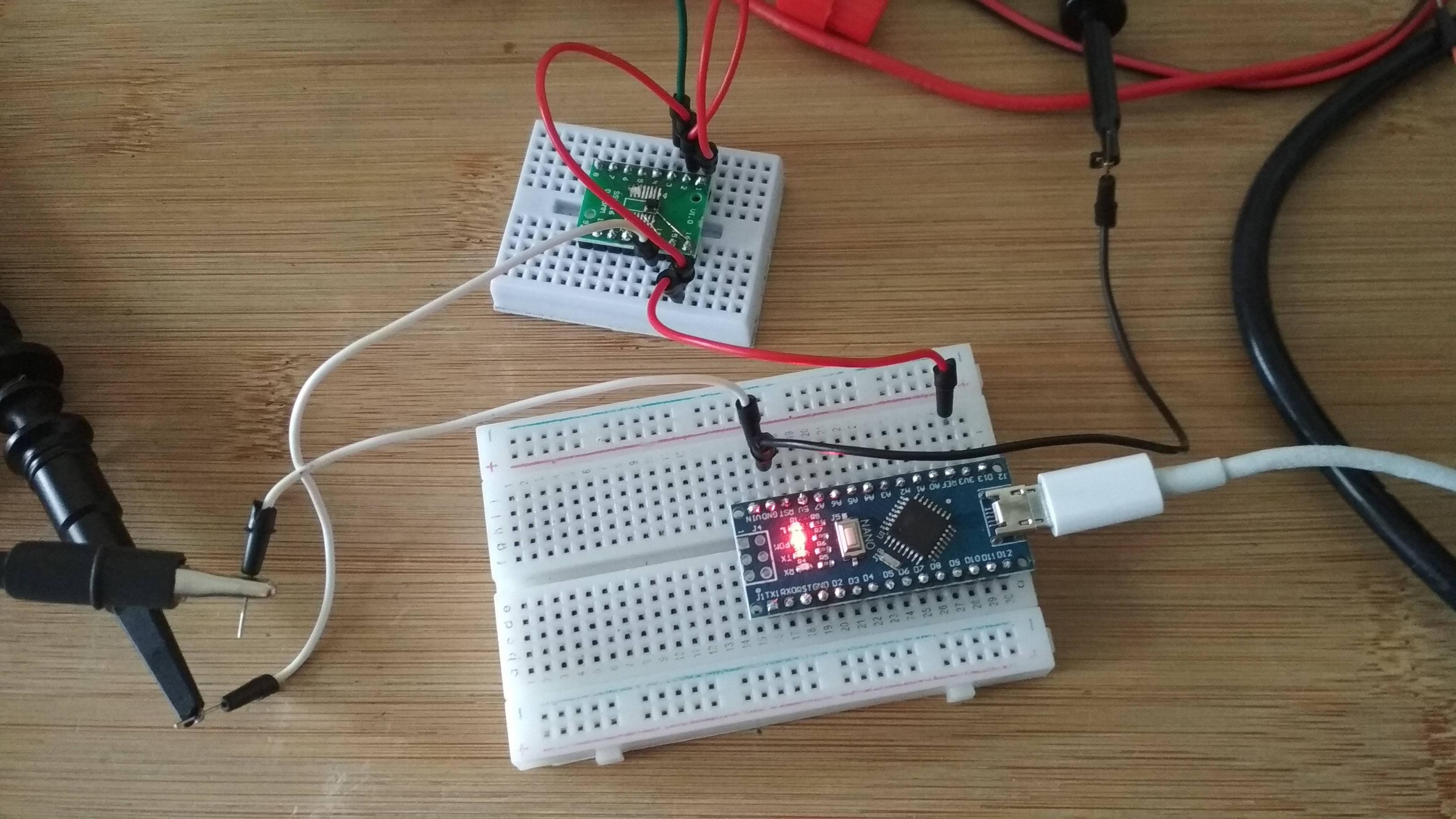
  • I power it with 3.3V from an Arduino knock-off
  • For the prototyping I use a breadboard
  • In order to measure the current I use a cheap multimeter PDM 300 C3 (it seems to display the current quite accurately since I tested it on some resistance with currents up to 1uA)

Here is what I have allready done to understand the problem:

  • I have tried to output a high value (3.3V) instead of a low value (0V) and there is no difference in the power consumption
  • I have tried to disconnect oscilloscope from the circuit and it also doesnt make any difference (infinite output impedance)

Here are some pictures of my setup: enter image description here
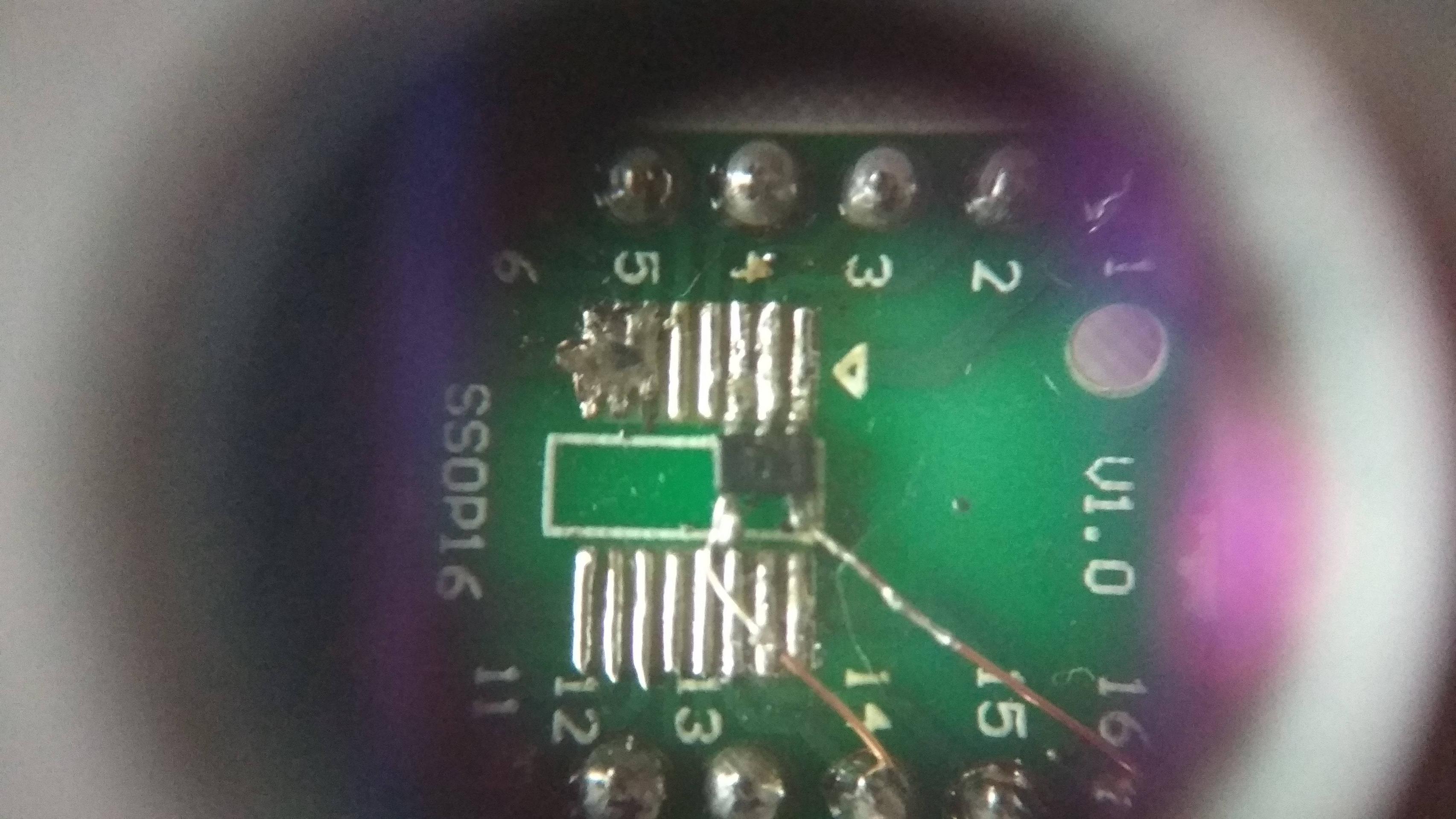
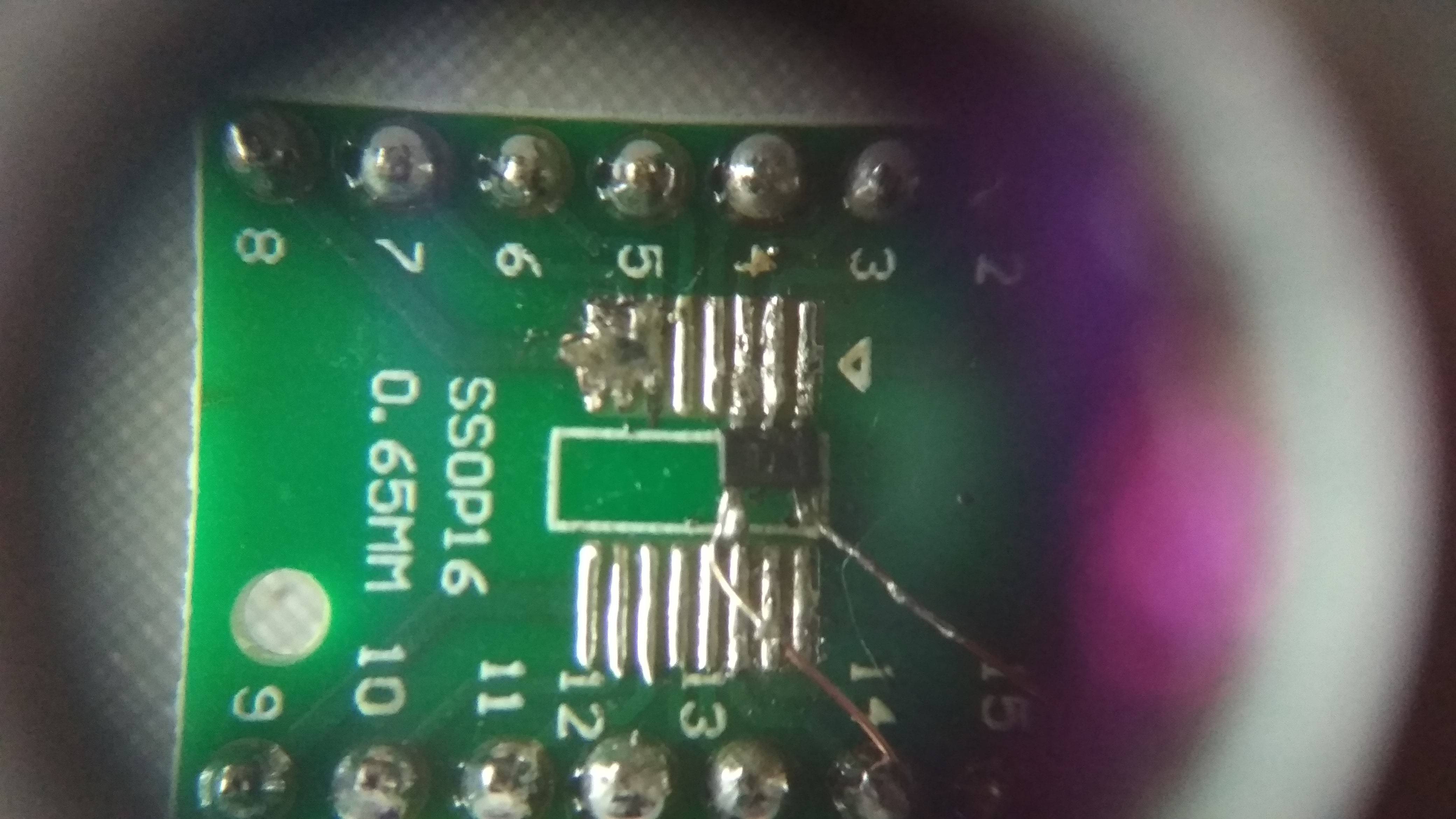
Here is the picture of the chip I soldered (I know the soldering is not so clean but all the terminals are connected as they should and there is no short circuit): enter image description here enter image description here
Finally, here is a very basic drawing of the circuit I use: enter image description here

I thank you in advance for you help,

Misha

\$\endgroup\$
9
  • \$\begingroup\$ Can you draw a schematic of your circuit? Where does the green jumper wire go? \$\endgroup\$ Commented Aug 5, 2023 at 15:27
  • \$\begingroup\$ Hello Spehro Pefhany, Thank you for your answer. The green jumper wire goes to the multimeter. I have added a picture of the circuit in the main question \$\endgroup\$
    – Log Dix
    Commented Aug 5, 2023 at 15:38
  • 1
    \$\begingroup\$ Hint: A power Supply the Arduino is NOT! \$\endgroup\$
    – Gil
    Commented Aug 5, 2023 at 16:01
  • \$\begingroup\$ I wince when I see the ampere-meter on the ground connection. (For one thing, it gets to measure not just supply current this way, but the sum of that and the input currents.) \$\endgroup\$
    – greybeard
    Commented Aug 5, 2023 at 16:05
  • \$\begingroup\$ Can you add a link to the data sheet that says max current draw is 0.9 uA? \$\endgroup\$
    – Sotto Voce
    Commented Aug 5, 2023 at 16:36

2 Answers 2

2
\$\begingroup\$

A long (=high inductance) wire in the GND of a logic IC is begging of troubles. Decoupling capacitor, say 100 nF with short, max. 1 cm wires between the supply voltage and GND pins of the logic IC can stop unpredictable behaviour.

A hint: You look a little more competent if you in addition move the current meter to the +voltage wire and have a short plain wire for the GND.

Added after comments:

If the output is stable (no oscillation) you may have a leak. To see it solder the IC off the circuit, but leave every other piece. Or your IC is faulty.

Too much heating during soldering, mains AC electricity leak from a low grade soldering iron and omitting static discharge precautions can cause easily semiconductor damages which occur as "drifted out of specs, varies with no apparent reason -behaviour". Solder flux residues (=washing omitted) can cause leaks.

It's practically impossible to find the actual reason here without having the system in my hands.

\$\endgroup\$
11
  • \$\begingroup\$ Hello Ormand, I applied your advices and soldered a 100nF capacitor between the +vcc and gnd and that didnt help unfortunately. Do you have any other idea from where the problem might come from ? \$\endgroup\$
    – Log Dix
    Commented Aug 5, 2023 at 19:51
  • \$\begingroup\$ Did you use electronic grade solder? \$\endgroup\$ Commented Aug 5, 2023 at 20:42
  • 1
    \$\begingroup\$ @Ormand It seems that the issue was with the flux indeed, now that I have cleaned the board with some IPA, the consumption has gone down very close to the datasheet power consumption and there is no more absurd current fluctuation. Thank you very much for pointing that out ! \$\endgroup\$
    – Log Dix
    Commented Aug 6, 2023 at 7:00
  • 1
    \$\begingroup\$ This is an indication that your flux-core solder is not electronic grade (or maybe you used non-electronic-grade flux in addition to the solder). Ordinary rosin-core solder will not do this. Plumbing acid flux will definitely do this. \$\endgroup\$ Commented Aug 6, 2023 at 13:03
  • 1
    \$\begingroup\$ @SpehroPefhany, yes I added some flux before soldering the components. The flux however indicates that it is electronic grade but then I didnt buy it in a electronic dedicated store \$\endgroup\$
    – Log Dix
    Commented Aug 7, 2023 at 18:58
0
\$\begingroup\$

The flux you've used "general purpose" is probably conductive. This can lead to relatively low resistance and fluctuating resistance. In the case of higher (eg. mains) voltages it can cause arcing. The reason for that is that general purpose flux is acidic so it has ionic conduction (which increases exponentially with temperature).

In this case try to clean it off with isopropanol and a toothbrush as much as possible, but in the future you should either discard the flux or mark it as unsuitable for electronics or electrical work.

\$\endgroup\$

Your Answer

By clicking “Post Your Answer”, you agree to our terms of service and acknowledge you have read our privacy policy.

Not the answer you're looking for? Browse other questions tagged or ask your own question.