I read this topic DMX on Arduino with RS485 and I want to use this in my new project.
Good to know is that my project concerns daisy chaining several DMX devices, so I need DMX IN as well as DMX OUT on every device.
These are my questions about what I read on the mentioned topic:
- the first schematic has 3 resistors, R1, R2 and R3, with funny values: 562 Ω and 133 Ω. What is meant by that (the second schematic has resistors with common values)?
- the second schematic has resistor R5 with value 470 Ω. Is that correct?
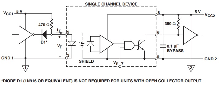
I checked the datasheet and I think the values 330 Ω and 470 Ω are mixed up. This is the recommended interface circuit as mentioned in the datasheet:
As you can see, the resistor on pin 2 has 470 Ω, the one on pin 6 has 390 Ω.
Or ... am I missing something? Please, correct me if I'm wrong.
- in my project I will try to implement this DMX circuit. I understand that this schematic is meant for a DMX IN connection.
I want to take this a step further and daisy chain several devices: I need a DMX OUT. What do I need for that? I expect I need another MAX485/481 chip. I'm unsure on how to do that. The same way as the first MAX485 by connecting RO, RE, DE and DI in parallel with the first one?

