1
\$\begingroup\$

I'm currently developing a DMX interface (master interface) with USB and Ethernet connections. The power for my device I'm retrieving from the 5V of the USB connector.

The shield of the USB connector and the Ethernet connector is connected with each other but hasn't any connection with the signal ground. I'm not sure if this is correct, so please correct me if I'm wrong!?

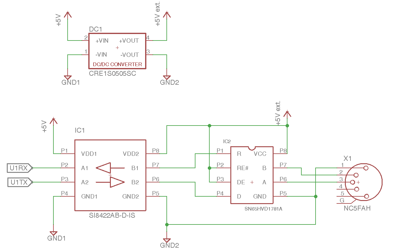
The DMX interface is decoupled with a DC-DC converter (CRE1S0505SC) and a digital isolator (SI8422AB-D-IS).

I'm now wondering what I should do with the shield of the XLR plug? Should I just connected it with the shield of the USB and Ethernet connector? Or isn't the device galvanically isolated anymore if I do that? The pin 1 of the XLR connector is connected with the ground of the DC-DC converter. But I think this should be correct.

The case of my device is plastic.

I know there are many threads in the internet about this. But I haven't found anything which describes my problem exactly. So I would be very happy if anyone could help me!

Edit: I have attached a simplified schematic.

Schematic

\$\endgroup\$
7
  • \$\begingroup\$ The shields of the connectors are connected to the screens/shields in the cables, if they are not connected to signal ground then they do not work to shield the signals properly, but they do not have to be dc-connected you can connect the shield(s) to the signal ground with caps \$\endgroup\$
    – user173292
    Commented Jan 3, 2018 at 20:43
  • 1
    \$\begingroup\$ This is a bit more complicated than Vinzent suggests. All depends on how the device is used, does it have user exposed connectors and hot-plug cables. For some details and considerations, see electronics.stackexchange.com/a/291380/117785 and electronics.stackexchange.com/a/269313/117785 \$\endgroup\$ Commented Jan 3, 2018 at 21:07
  • \$\begingroup\$ @AliChen: I have read your answers. But I'm still not sure, what I should do. My device is a portable device with a USB, Ethernet and XLR connector. \$\endgroup\$ Commented Jan 3, 2018 at 21:23
  • 1
    \$\begingroup\$ Typically, for portable stand-alone devices, people use one solid plane for signal ground and shield. But if your device must be always connected to a PC host to work, shield should be routed separately, it will join the signal ground at PC side. I would recommend to route them separately, but connect them with zero-ohm jumpers (or use a cut option). Then, if you have issues with EMI or ESD, you cut these jumpers and add whatever RLC parts that solve the issue. Geometry and electrical field configurations are fairly complicated in 3D, so you never know. \$\endgroup\$ Commented Jan 3, 2018 at 22:26
  • \$\begingroup\$ @AliChen: OK. Thanks for the reply. But the USB and RJ45 (Ethernet) shield are connected with each other? If I understand you correctly you would use no cap's, as mentioned by Vinzent, rather you would directly connect shield and ground (but with a cut option)? \$\endgroup\$ Commented Jan 3, 2018 at 22:51

2 Answers 2

2
\$\begingroup\$

Generally electrical shielding only works if it is connected to ground (the ground of the stuff its supposed to shield) and the shields of the connectors are connected to the screens/shields in the cables, if they are not connected to signal ground then they do not work to shield the signals properly, but they do not have to be dc-connected you can connect the shield(s) to the signal ground with capacitors.

\$\endgroup\$
8
  • \$\begingroup\$ OK. And what capacitors do you would recommend? Or how can I calculate the size of the capacitor? \$\endgroup\$ Commented Jan 3, 2018 at 20:51
  • \$\begingroup\$ Use capacitors with very low ESR preferably ceramic capacitors, you don't need a very big cap I think 1u would probably do however it is recommended to use multiple capacitors like don't use one 1u use 10* 100n is much much better. \$\endgroup\$
    – user173292
    Commented Jan 3, 2018 at 20:54
  • \$\begingroup\$ OK. Just to be clear: You would connect the shield of the USB and Ethernet connector with each other and then connect it with a capacitor to my signal ground? The shield of the XLR connector should also be connected to the (second) signal ground with a capacitor. But the shield of e. g. the USB and XLR plug has no connection. Am I right? \$\endgroup\$ Commented Jan 3, 2018 at 20:59
  • \$\begingroup\$ Well almost right, usually you have a ground and a shield and the shield is common and often also connected to a metallic housing that also works as a shield. often times all the connectors will be mounted in a metallic enclosure that connects them electrically and you just connect your common shield to your common gnd with capacitors. the way many do it is that they have screw holes with pads arround them and those connect to the casis through the screws and at each pad/screw-hole you place a capacitor, and then you also place capacitors to the shields of the PCB mounted connectors.. \$\endgroup\$
    – user173292
    Commented Jan 3, 2018 at 21:05
  • \$\begingroup\$ ..but in short unless your application requires otherwise the shields are usually all connected as a "common shield" \$\endgroup\$
    – user173292
    Commented Jan 3, 2018 at 21:06
1
\$\begingroup\$

The major concern with DMX specifically is the potential for a screwup somewhere in the rig to dump mains onto the DMX line, it shouldn't happen, but moving equipment, lots of temporary cable, hot lights... It does.

Now contrary to others here, a correctly made DMX cable will generally not connect the connector shell to the screen, inferior from a RFI perspective maybe, but 250KBaud RS485 is stupidly robust so I would probably either use a platic XLR socket or leave the thing floating, What you do NOT want is it connected to the computer via a USB cable or STP cable, USB ground in particular does not generally do well with a few tens of amps of mains up it.

If I was doing the cap thing, it would be smallish and class Y, with maybe a few Meg ohms across it.

\$\endgroup\$
5
  • \$\begingroup\$ So what do you would recommend for my DMX circuit? Just leave the shield pin floating or use a cap? \$\endgroup\$ Commented Jan 3, 2018 at 22:48
  • \$\begingroup\$ Pin 1 goes to the isolated 0V line powering the RS485 driver, this is important to control the common mode see by the receivers. The connector shield? I would leave it floating in the first instance. I would probably put a few meg ohms across the isolation barrier to bleed off any static and might think about at least putting in the footprint for a nF or so of class Y cap. \$\endgroup\$
    – Dan Mills
    Commented Jan 4, 2018 at 10:58
  • \$\begingroup\$ Yes, I've meant the connector shield. The pin 1 of the connector was already clear to me. Thank you for the response. \$\endgroup\$ Commented Jan 4, 2018 at 11:10
  • \$\begingroup\$ @DaniMills: I'm currently wondering if the connector shield shouldn't be also connected to ground? Note that my devices is the DMX master deivce! Because I think, if the connector shield isn't connected, isn't the shield useless? \$\endgroup\$ Commented Jan 5, 2018 at 21:14
  • \$\begingroup\$ The connector shield is normally left floating at least from the cable side because a few inches of unshielded twisted pair is a smaller issue then the potential for large circulating currents. Given this it mostly does not much matter, but in the absence of a secure mains earth I would keep it well away from things like USB just in case someone has an incorrectly made cable (Class Y and 1Meg res might be a reasonable compromise). Note that fast RS485 drivers are a notably bad idea for DMX which only runs 250kBaud, dont use 20 or 50Mb/s drivers for this, pick something slew rate limited. \$\endgroup\$
    – Dan Mills
    Commented Jan 6, 2018 at 13:51

Your Answer

By clicking “Post Your Answer”, you agree to our terms of service and acknowledge you have read our privacy policy.

Not the answer you're looking for? Browse other questions tagged or ask your own question.