Depending on your EL driver box input voltage, you have a few options. All are based on usign a simple P-channel MOSFET as a switch. Note that all values and part numbers are just guidelines, any general purpose NPNs will do, similarly any general P-ch MOSFET will do (as long as it has a low enough threshold voltage, e.g. < 3V or so, and can handle the maximum EL box current easily - check the rating)
Also resistor values are not set in stone, you have considerable leeway with the values here also (the 2.2kΩ R_PULLUP is a guess at the gamepad pullup)
For example, R1 could be anywhere between, say, 10kΩ and 1MΩ (the higher the impedance the more prone to noise, the lower, the higher power consumption and the harder for the transistor in the last circuit to pull down)
EDIT - Okay, now we know the voltages, then we can settle on this circuit. I will leave the rest of the circuits below in case they are of any use to future readers.
This assumes that the EL wire driver supply is always a bit lower than the gamepad supply:
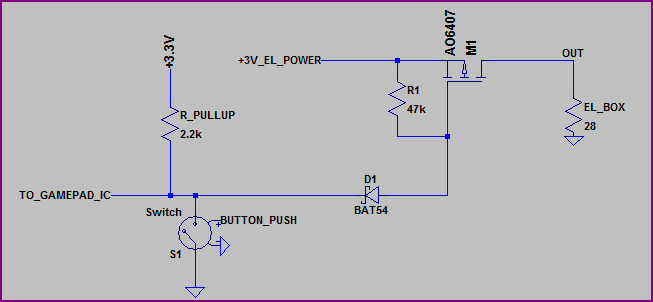
Make sure you choose a MOSFET with a low Vth (turn on threshold voltage) and use a schottky diode (make sure it is the right way round) The EL Driver supply and Gamepad supply ground wires need to be connected. The Switch represents the button, R_Pullup the assumed internal gamepad resistor, and the +3.3V represents the gamepad supply.
Simulation:
Circuits below left for interest to future readers
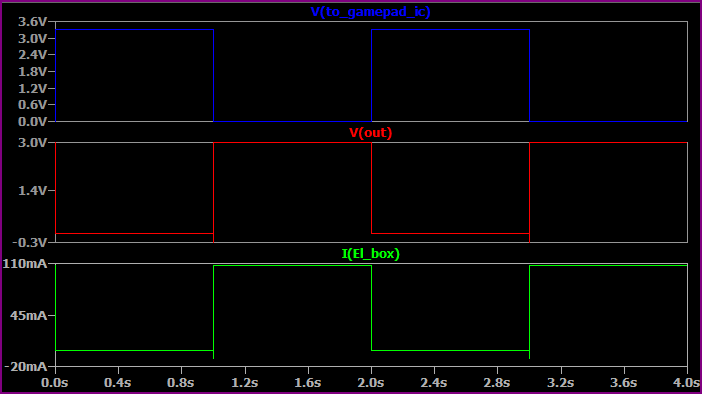
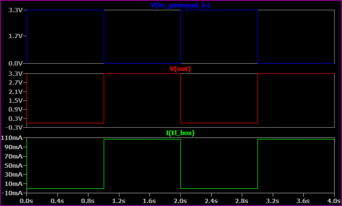
If the input voltage is +3.3V, then things are very easy, this circuit will work (note - this assumes two 3.3V regulated supplies that are not going to vary by more than a couple of percent):
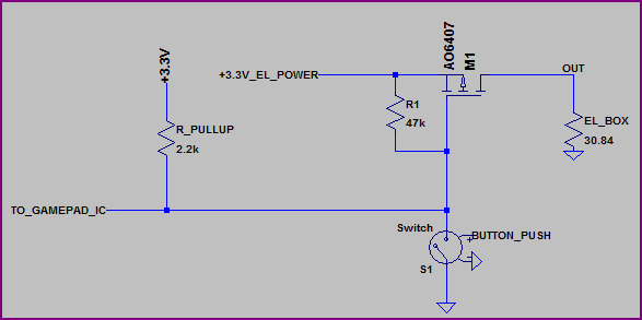
EL_BOX is a simple representation of the load from the EL driver box. When the button is pushed it pulls the gate of the P-ch MOSFET low and turns it on, supplying power to the EL driver.
Simulation:
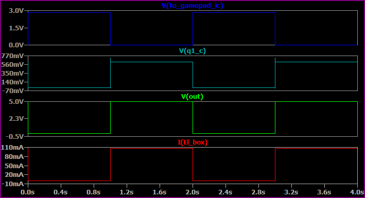
If the voltage of the EL wire box is different, let's say 5V, then if you can hack a schottky diode in between the button and it's +3.3V connection, then this circuit would be an option:
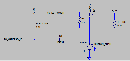
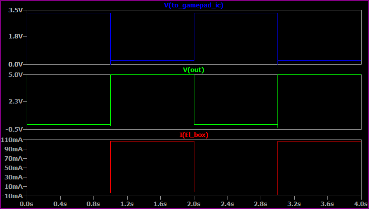
The diode prevents the 3.3V rail interfering with the 5V rail, but still allows both to be pulled to (near) ground. A schottky is used as it has a lower drop than a normal silicon diode, to make sure the game controller IC pin sees a logic low.
Simulation:
If it's not possible to hack the diode in (i.e. all you have access to is the +3.3V line and ground line) then you will need a couple of transistors to invert the signal something like this:
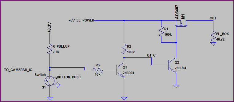
You could use N-ch MOSFETs for Q1 and Q2, but bipolars are cheaper so unless you need the lowest power consumption NPNs will do fine.
Simulation:
