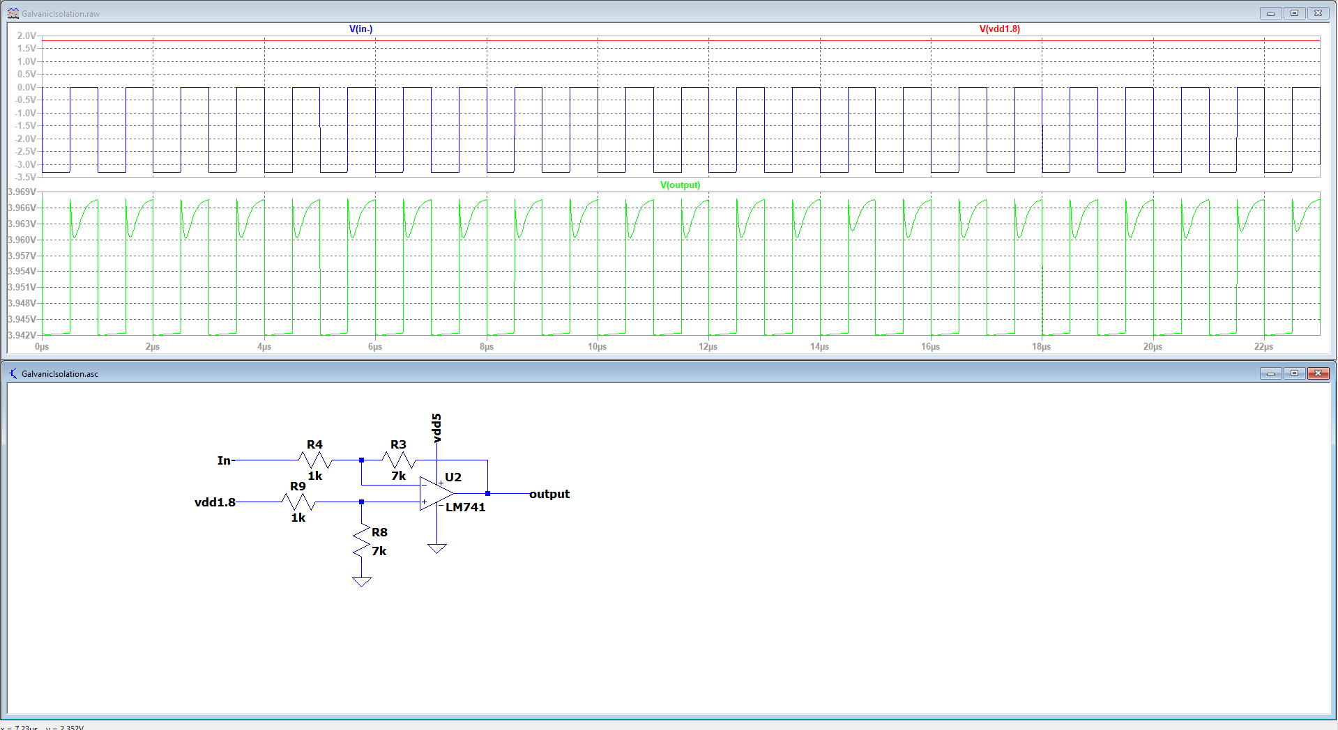
I am trying to build a differential amplifier using the lm741 op amp, and simulate it in LTSpice. The dynamic range of the output is too small (about 20mV), I use a rectangular wave (3.3V) and 1.8V DC Input and want to amplify this input difference. Anybody knows the reason, why the output dynamic range is too small?
Thanks in advance,
Ahmed
-
3\$\begingroup\$ What are your supplies? You are almost certainly using supply voltages that are two small -- you need a negative rail because the 741 can't drive its output all the way down to the negative rail (in this case, ground). \$\endgroup\$– Null ♦Commented Mar 3, 2022 at 15:00
-
1\$\begingroup\$ 1) You need split supplies of typically about +/-15V, but note that a 741 cannot get all the way there. (2) with a voltage gain of 7, and 3.3V in, you expect about 23V out - can your opamp do this with the supplies you give it? (3) note your input is DC coupled, think about the DC level on each input, and what the output is trying to do. \$\endgroup\$– danmcbCommented Mar 3, 2022 at 15:18
-
1\$\begingroup\$ Some relevant background reading about 741 op-amp behaviour / limitations: "Reasons not to use a 741 op-amp?" \$\endgroup\$– SamGibson ♦Commented Mar 3, 2022 at 15:37
-
2\$\begingroup\$ Bury the antique 741 opamp. \$\endgroup\$– AudioguruCommented Mar 3, 2022 at 15:57
-
2\$\begingroup\$ @RichS While I'm sympathetic to criticisms of the antique LM741, it has weaknesses that are reflected in more modern op-amps. OP really needs some kind of metric to zero in on the specs that matter. Suggesting a more modern op-amp that is inadequate because it has a 2.5MHz GBW (OPA196) does not really help things, IMO. It's 2.5x better, but still nowhere near good enough. And it won't give the calculated ~35V output with a 5V supply, of course. \$\endgroup\$– Spehro 'speff' PefhanyCommented Mar 4, 2022 at 23:04
3 Answers
You're using the poor 741 way beyond what it can do: switching at 1 MHz. If you'll go to My Documents/LTspiceXVII/examples/Educational/ you'll see LM741.asc. It's a transistor level representation. If you then change the input source to be PULSE(0 1 0 10n 10n 0.5u 1u) and simulate for .tran 10u, you'll see a more likely output of how the opamp should behave. Not only it's not a comparator, but it's a very fat and lazy opamp, too. What you have there is not a god model. Caveat emptor: always test your models.
-
2\$\begingroup\$ Not to mention trying to use a 741 with a single 5 volt supply. I'm mildly surprised he gets anything out at all. No, let me take that back. What he's seeing is simply feedthrough from the input to the output. \$\endgroup\$ Commented Mar 4, 2022 at 21:02
-
1\$\begingroup\$ @WhatRoughBeast Many opamps rely on some basic SPICE topology that originated many years ago and use only primitives. It's not difficult to tweak the settings to get an
.ACresponse, but for a.TRANthey will fail at many characteristics. While that's not necessarily a bad thing (if.ACis your only concern), it does tend to propagate the idea of "pick and place", without any form of testing. This is the part that should really be addressed, but it requires a bit of preemptive thinking which, unfortunately, is not so often found. \$\endgroup\$ Commented Mar 4, 2022 at 21:52
From looking at the schematic, I'm assuming that vdd5 is 5V.
The amplifier has a gain of 7. So the difference between the vdd1.8 node (1.8V) and in- node will be multiplied by 7.
The signal coming to in- node is a pulse train. Let's analyse it:
- When the signal is zero the difference signal will be 1.8 - 0 = 1.8V. Expected output is 1.8 x 7 = 12.6V.
- When the signal is -3.3V the difference signal will be 1.8 - (-3.3) = 5V. Expected output is 5 x 7 = 35V.
As you can see, in either case, the output will exceed the supply voltage of op amp, which is presumably 5V. The LM741 is not a rail-to-rail op amp thus the output will be (probably a few hundreds of millivolts) less than 5V. So the circuit behaves as expected.
Decrease the pulse train's amplitude and increase the supply voltage because none of the 741's are supposed to be supplied from 5V.
-
3\$\begingroup\$ RE: "thus the output will be (probably a few hundreds of millivolts", for the 741 it won't get within a few hundred millivolts. It needs more like a volt of headroom. In the TI datasheet, only +/- 12 V output swing is guaranteed with a +/- 15 V supply, and +/- 14 V is typical. \$\endgroup\$ Commented Mar 3, 2022 at 15:37
-
\$\begingroup\$ @ThePhoton thanks for the info. I was too lazy to check the datasheet. \$\endgroup\$ Commented Mar 3, 2022 at 16:02
-
\$\begingroup\$ A 741 switching at 1 MHz? I'm quite surprised the output looks like that, which makes me believe it's not a very good model. \$\endgroup\$ Commented Mar 4, 2022 at 19:25
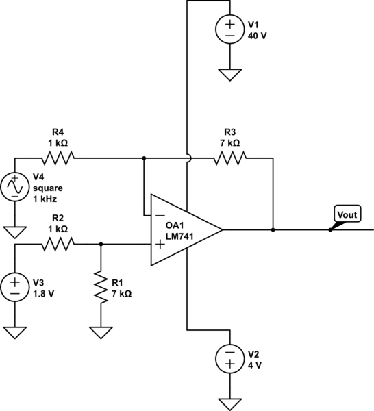
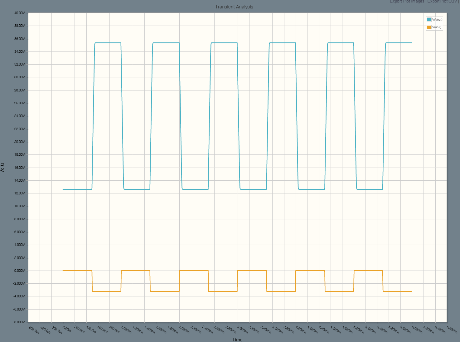
Here is what the output should look like (roughly) with an LM741, but I've changed the supplies to +40/-4 and reduced the frequency to 1kHz, a more reasonable frequency for the LM741 and square waves.

simulate this circuit – Schematic created using CircuitLab
The peak output voltage is 7 * (1.8 + 3.25) = 35.35V. The minimum is 7 * 1.8 = 12.6V (a popular vacuum tube heater voltage at one time).
A 741 will barely manage to output a sickly low-amplitude triangle wave if you feed it with a large square wave input at 1MHz. It's orders of magnitude away from being capable of handling that kind of frequency. In fact you'd need a very high frequency op-amp to amplify a 1MHz square wave x 7 and have it come out looking more or less like a square wave. Perhaps 70 MHz gain bandwidth, and adequate slew rate vs. about 1MHz GBW for the 741.
What you are seeing in the simulation is just some internal coupling at low amplitude. The op-amp is doing nothing of value (it's railed).

