2
\$\begingroup\$

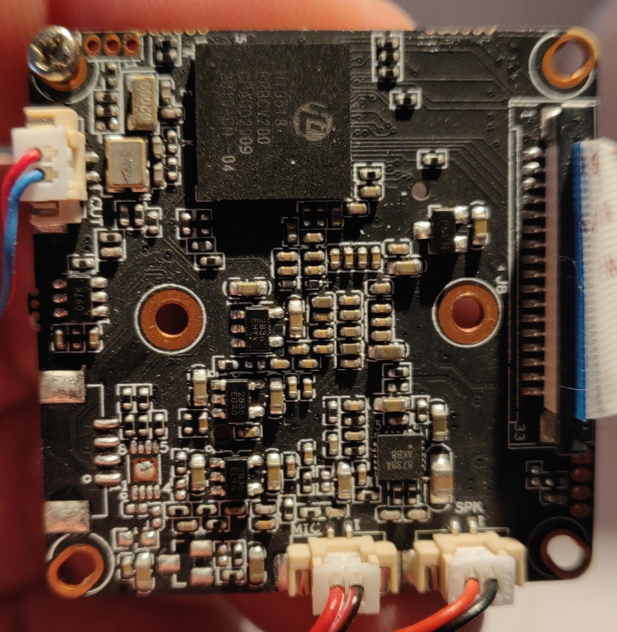
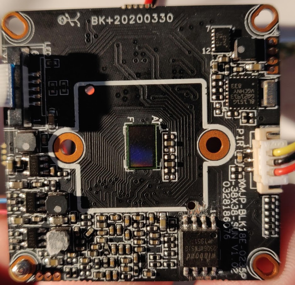
I am trying to reverse engineer a cheap Chinese Hi3518ev200 based camera for quite some time now. I have successfully located the UART used for the serial console (3 pins lower left on the picture), but am struggling finding an USB port the operating system detects. Maybe it's just not connected.
However, a 4 holes port is available but I can't figure out what it could be, upper right on the picture 3518ev200 based ip camera

Both pairs output continuous 1.8v when the board is powered on, probed in both a multi meter and a basic oscilloscope.
Any idea on what this port could be?

CPU Side View

CPU side view

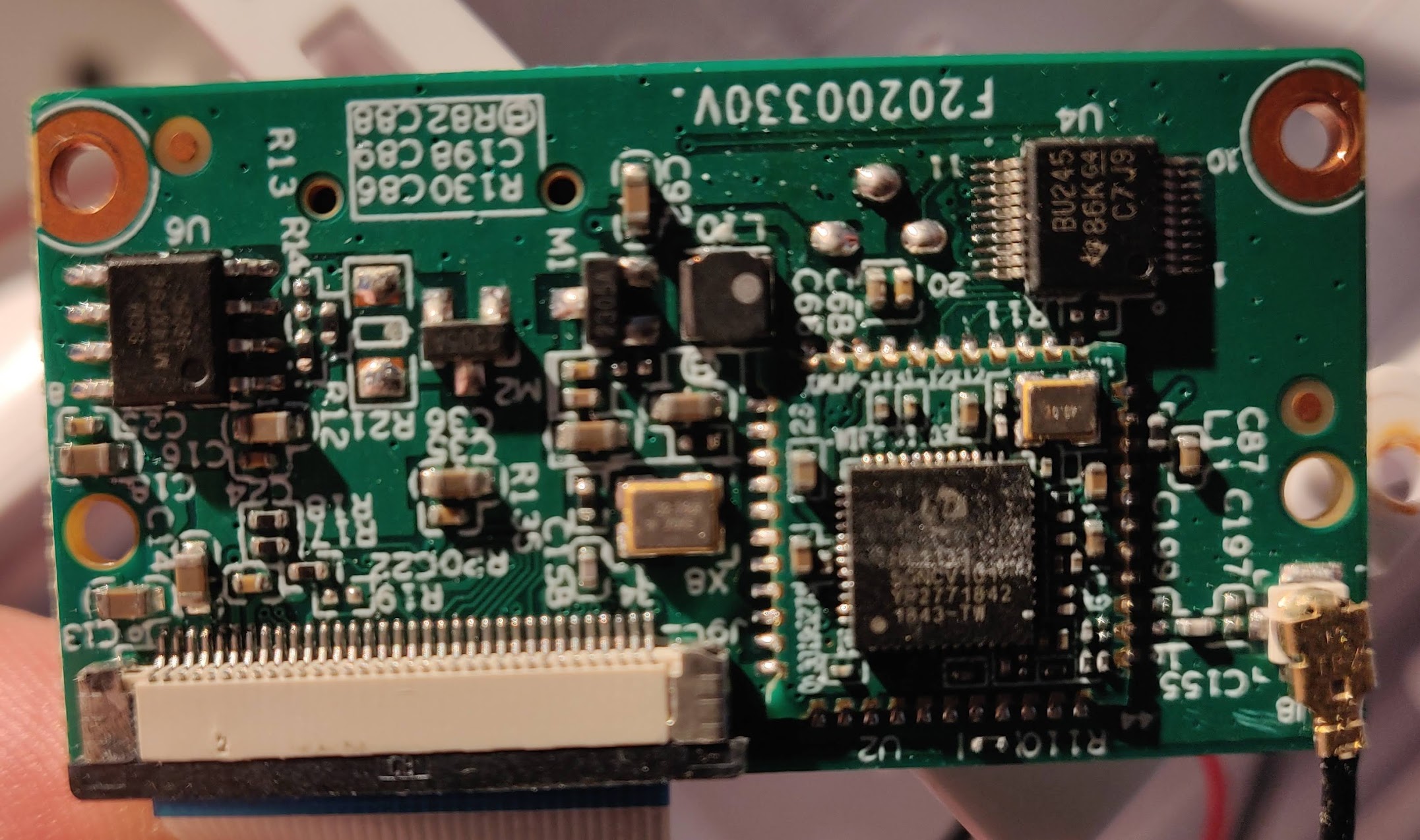
WiFi Chip Satellite

WiFi chip satellite

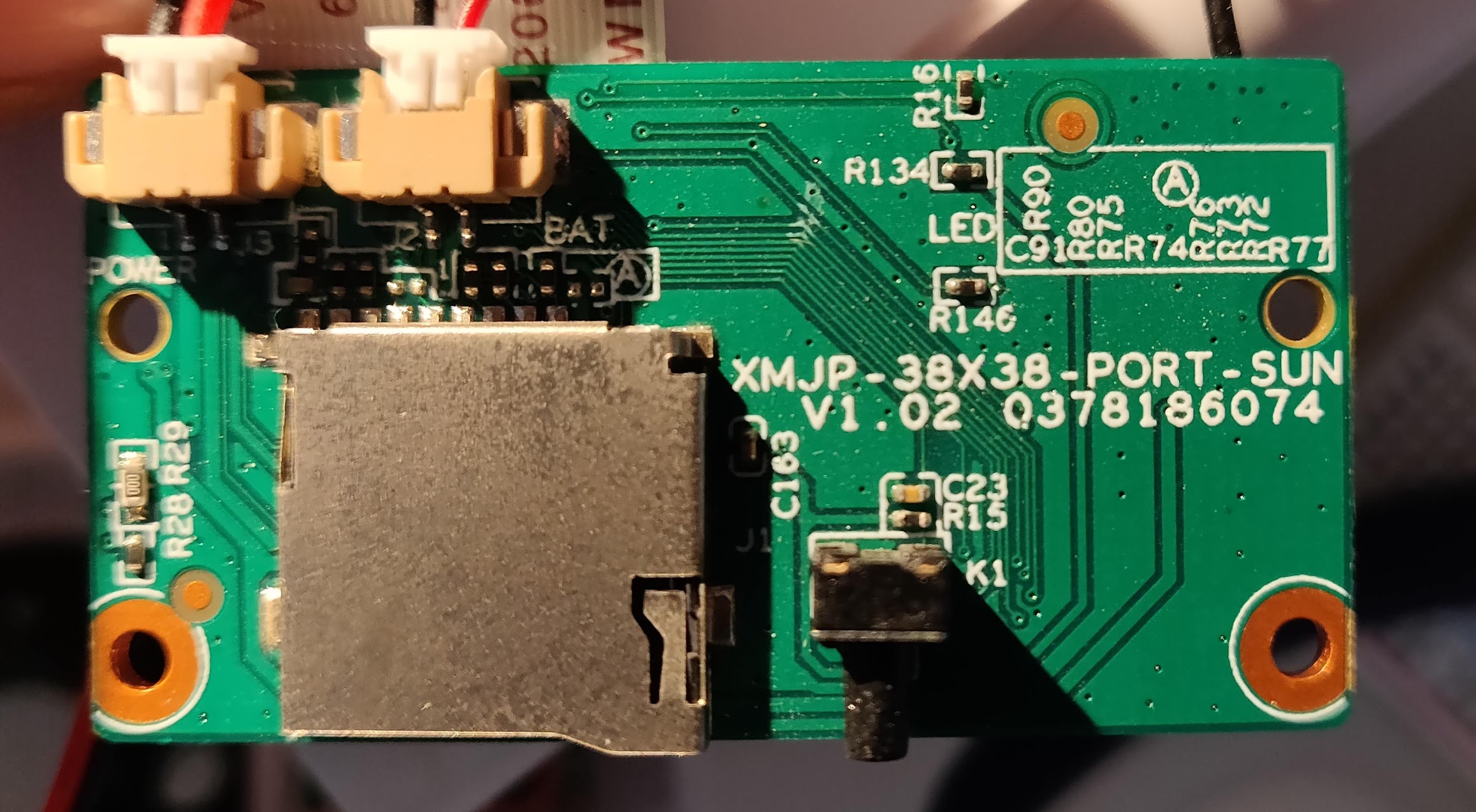
Micro SD Side

Micro SD side

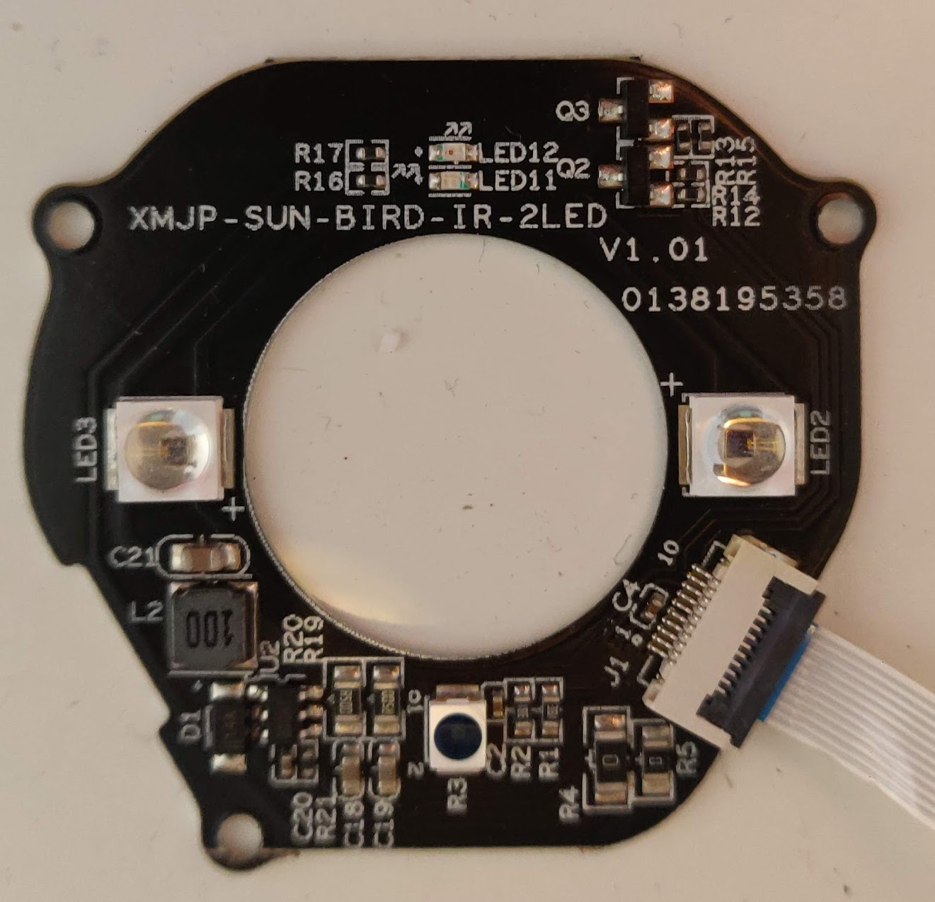
LED Board

LED board

\$\endgroup\$
3
  • 1
    \$\begingroup\$ What do you mean with "a USB port the OS detects"? I mean, you seem to connect the camera to a PC via USB somehow. Which connector do you use for that connection? \$\endgroup\$
    – Sim Son
    Commented Mar 12, 2022 at 14:04
  • \$\begingroup\$ @SimSon no it's a standalone ip camera, but Linux's dmesg says there's an USB port and even attaches an ethernet interface to it \$\endgroup\$
    – iMil
    Commented Mar 12, 2022 at 16:51
  • 1
    \$\begingroup\$ Next step would be to figure out where these pins connect to. If they connect to the uC, its datasheet can give you a hint which interface could be used on these pins. \$\endgroup\$
    – asdfex
    Commented Mar 12, 2022 at 17:08

1 Answer 1

1
\$\begingroup\$

Not a full answer, but too long for a comment.

First of all, have you identified the voltage with respect to ground? When you say "both pairs output 1.8V", do you mean that voltages (refered to ground) are 0V (rectangular pad), 1.8V, 0V, 1.8V ? Or something else.

Anyway, the voltage 1.8V in itself alredy interesting : it's a common logic voltage level in new logic circuits (many modern micro-processors and micro-controlers for low power applications). However, due to low voltage, it is also more sensitive to noise, so not well suited for long wires. So this is a (weak) hint toward debug/configure/program/... port rather than a user interface.

You also say that you measured 1.8V with the scope, so I suppose you mean 1.8V DC. If so, I see 4 main options :

  • it is an output signal, which never changed durring your tests (maybe because you have to somehow configure it first)
  • it is an input signal, with a pull-up to 1.8V
  • it is some bidirectionnal signal (like I2C) with pull-up
  • it is just a power supply

I would suggest to try to find out if there is a pull-up involved : measure precisely the voltage of the pin. Then add a 100k resistor between the pin and ground, and see if the voltage goes down. With 100k, the likelihood of damaging something is rather low (on the other hand, the pull-up might be a few kohms only, so the voltage different might be as low as 1
\$\endgroup\$

Your Answer

By clicking “Post Your Answer”, you agree to our terms of service and acknowledge you have read our privacy policy.

Not the answer you're looking for? Browse other questions tagged or ask your own question.