1
\$\begingroup\$

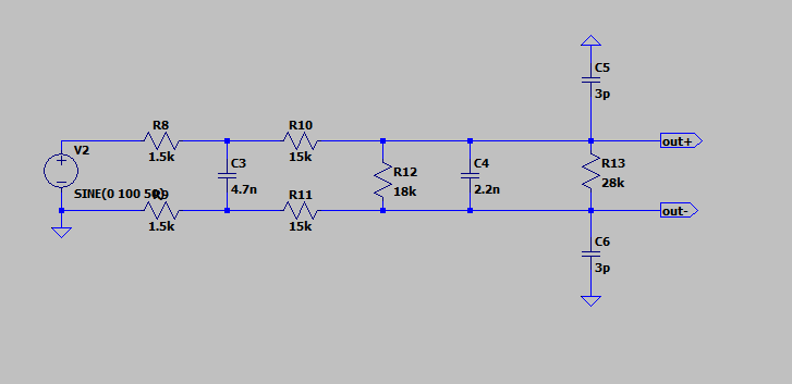
I'm stuck trying to calculate the cut-off frequency and transfer function of the filter below.

I'm not sure how to handle the mirrored resistors on the bottom (R9, R11) or the extra resistors (R12, R13).

New to electronics so any advice would be helpful.

enter image description here

[Edit] I've tried remodelling the circuit like this to run through a 2 pole Rc filter calculator but not sure if it is correct

enter image description here

Thanks!

\$\endgroup\$
6
  • \$\begingroup\$ Brute force: Just do nodal analysis on every node and solve for it. You can't use the voltage divider anymore. \$\endgroup\$
    – Designalog
    Commented Mar 23, 2022 at 14:26
  • \$\begingroup\$ Do you know reduction methods to convert differential to single ended? \$\endgroup\$
    – D.A.S.
    Commented Mar 23, 2022 at 14:46
  • \$\begingroup\$ What does your simulator tell you? \$\endgroup\$
    – Andy aka
    Commented Mar 23, 2022 at 15:35
  • \$\begingroup\$ Why don't you run a simulation and see what it says? Is this a question for your college coursework? Have you made any effort to solve this yourself, and if so, please show your work. \$\endgroup\$ Commented Mar 23, 2022 at 16:24
  • \$\begingroup\$ Hi everyone, thanks for the responses. running the simulations shows me it's frequency dependant and I get a lot of attenuation at higher frequencies. At low frequencies I can use the potential divider and get the output I expect. I've made an edit to show the model I've tried simplifying too. For context, it's not coursework, I'm trying to map readings I'm getting on an ADC back to a current sensor. \$\endgroup\$ Commented Mar 23, 2022 at 16:36

2 Answers 2

1
\$\begingroup\$

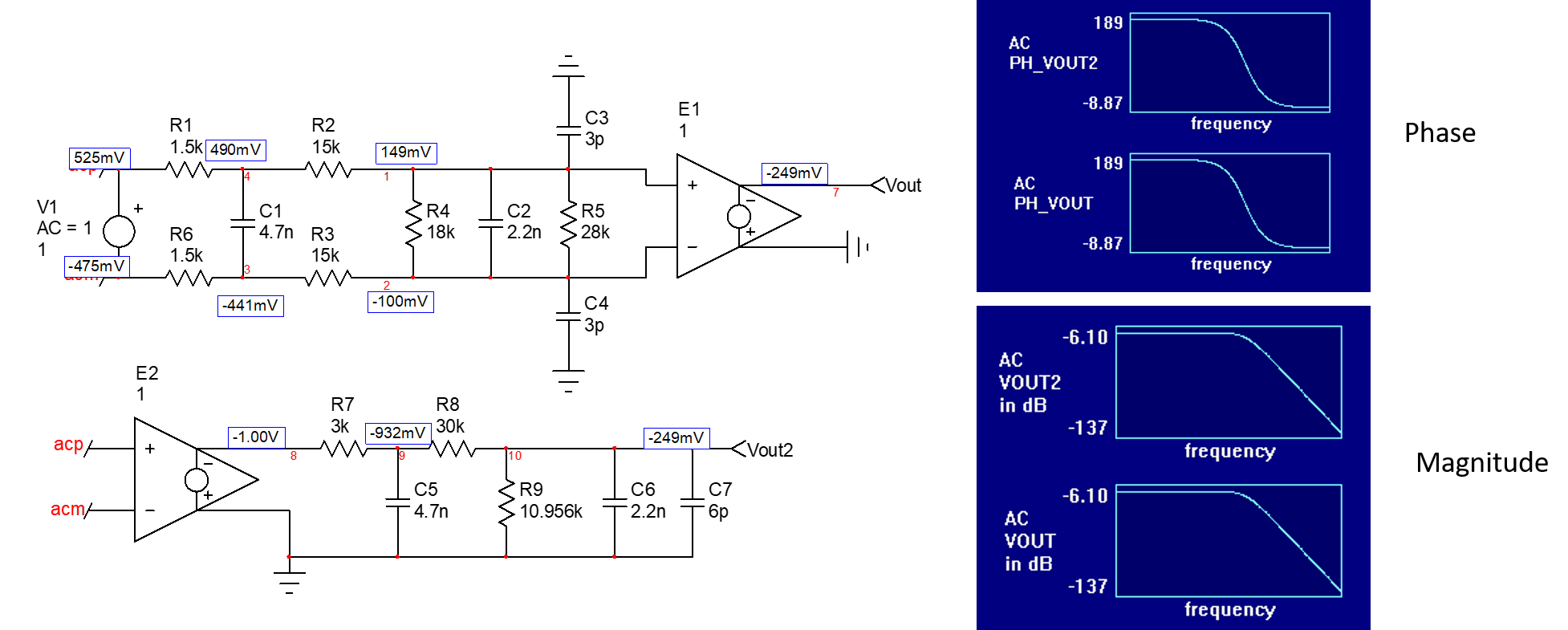
You can certainly use a simulator to find the equivalent circuit when removing the differential configuration:

enter image description here

Once you have a working equivalent schematic (same ac and dc responses), then you can start the analysis of this second-order filter. I will neglect the 6-pF contribution which comes across the 2.2-nF capacitor:

enter image description here

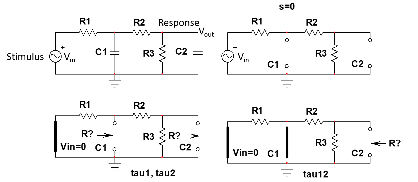
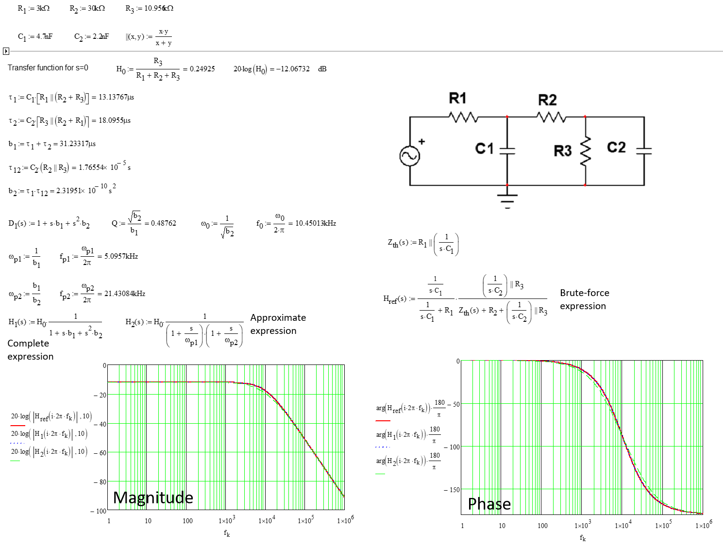
The easiest and fastest path here is to apply the fast analytical circuits techniques or FACTs as described in my book. Without writing a single line of algebra, just by determining time constants by inspection, you can determine the transfer function of this circuit easily. The maths details are given below:

enter image description here

\$\endgroup\$
2
  • \$\begingroup\$ Thanks for the extremly detailed answer! \$\endgroup\$ Commented Mar 24, 2022 at 15:45
  • \$\begingroup\$ No problem at all, glad if this is helpful. You can download from my page a seminar I taught in 2016, APEC 2016 which offers a smooth introduction on the subject. \$\endgroup\$ Commented Mar 24, 2022 at 17:23
0
\$\begingroup\$

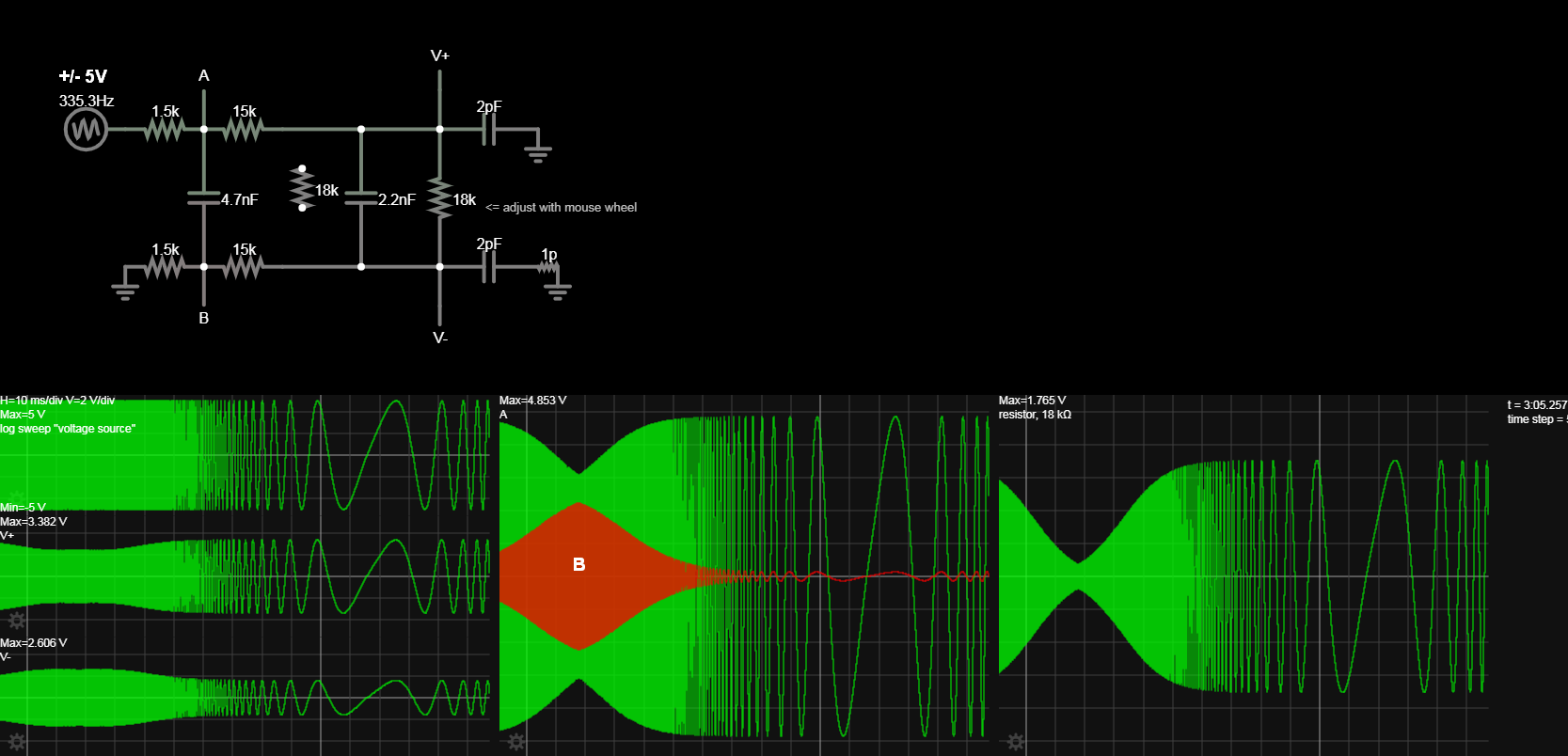
I extended the range 20 Hz to 24 kHz to show the single ended nodes A,B, V+,V- a differential load with one redundant R removed.

My simulation.

enter image description here

What are your expectations?

\$\endgroup\$

Your Answer

By clicking “Post Your Answer”, you agree to our terms of service and acknowledge you have read our privacy policy.

Not the answer you're looking for? Browse other questions tagged or ask your own question.