0
\$\begingroup\$

I have an IC with integrated gate driver. This IC has an integrated logic, charge pump and gate driver section.

Unfortunately, the rated voltage of my application is higher than the ICs rated voltage. I was wondering if I could add gate drivers that can switch an H-bridge at a higher voltage and make it work for my application.

I have figured out how to wire up the bottom side outputs of the gate driver, but I can't figure out where to connect the floating pin of the high side gate driver to get the system to work.

Has anyone else done this before?

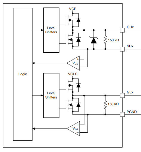
I'll add more details: I am trying to drive the MP1906 gate driver from the output of a BLDC predriver IC. Here is the block diagram of the BLDC predriver gate driver section.

enter image description here

Here is the pinout of the MP1906 gate driver: enter image description here
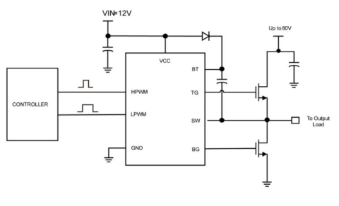
I figured out that I need to connect the GLx pin to the LPWM pin on MP1960 and GHx to HPWM but how should I connect the SHx pin to get the system to work correctly?

\$\endgroup\$
1
  • \$\begingroup\$ Take a look at this. Its a 600V half-bridge gate driver \$\endgroup\$ Commented Apr 3, 2022 at 7:01

2 Answers 2

1
\$\begingroup\$

You cannot use external gates directly for H-bridge to increase max voltage limit. It can be used for more current loads.

For higher-voltage, you'll need to compose an H-bridge with photocoupler - isolated, and drive those photocouplers with the IC's bridged output.

\$\endgroup\$
1
  • \$\begingroup\$ You don't really need a photocoupler. International Rectifiers has half-bridge gate drivers rated for 600V. Use 2 of those for full bridge. \$\endgroup\$ Commented Apr 3, 2022 at 6:58
0
\$\begingroup\$

this gate driver does exactly have a charge pump it has a bootstrap which charges up the floating cap for the high side when low side is ON and then flies up in when low side turns off.

if you are going to add another half-bridge driver in front of it you should tie SHx to PGND so they are both referenced to same gnd.

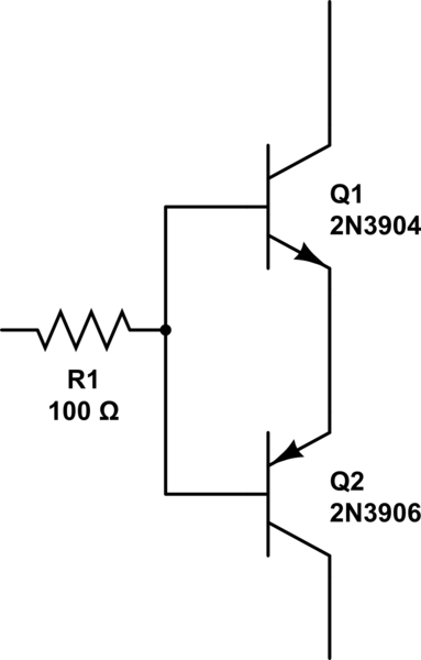
if it were, i would avoid doing that and just add a bipolar pushpull buffer to each channel and save yourself some time and money, assuming the bldc driver is rated for the bus voltage.

schematic

simulate this circuit – Schematic created using CircuitLab

\$\endgroup\$

Your Answer

By clicking “Post Your Answer”, you agree to our terms of service and acknowledge you have read our privacy policy.

Not the answer you're looking for? Browse other questions tagged or ask your own question.