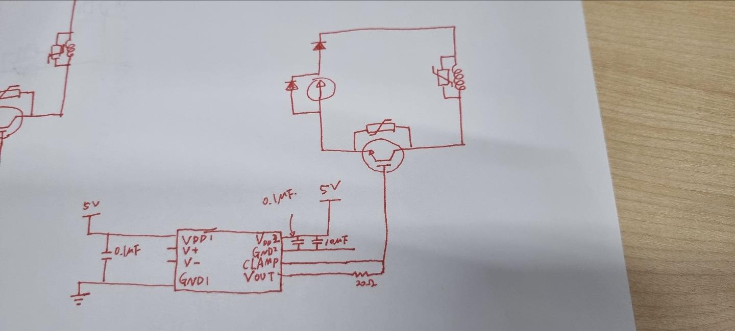
I tried to use IGBT (skm400ga-12t4) to do fast current switching of circuits with an inductor. The gate driver used adum4121-ARIZ and gate driving was performed by making a same circuit to the example in the data sheet.
Currently, one of the four IGBTs I have had was fine with gate driving even if 150A current was applied to the coil, but the other three had problem. Symptoms of three problematic IGBTs are as follows.
Gate driving works well up to 30A, so I think the gate driver needs protection or I use it more than specifications of parts (IGBT or gate driver), but I don't know where the problem is. The current flowing through the coil (inductor) did not have a problem up to 30A, but adum-4121 shows problem around 50A, and Vout only came out at 3V. Even if I changed the gate driver, it broke down again. I checked that gate driver worked well at first and the ampere was output properly when I applied 50A or higher. However, gate driving did not work properly when the second test was conducted, and the reason was that Vout is only 3V. Maybe the gate driver will have a problem when the current decreases.
Gate driving works well up to 30A, so I think the gate driver needs protection or I use it more than specifications of parts (IGBT or gate driver), but I don't know where the problem is. Of course other possibilities may be the 3 IGBTs problem. But it's so strange that 3 out of 4 have functional defects.
Could you help me find out what the problem is?

