1
\$\begingroup\$

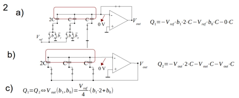
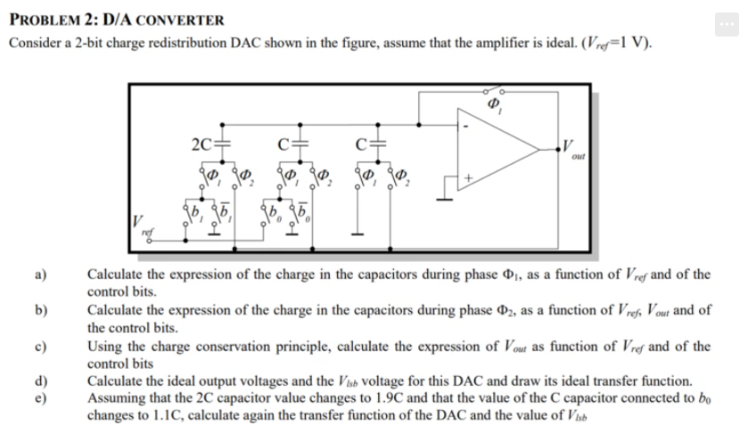
So here is the circuit:

enter image description here

And here is the output:

enter image description here

I presume answer c) is the output when there's a transition from phase 1 to phase 2. What about the transition from phase 2 to phase 1?

Vout will be equal to 0 because of the non inverting input being a virtual ground, why is this case ignored? 0 is being sampled, that makes non sense in a dac

\$\endgroup\$

1 Answer 1

0
\$\begingroup\$

What about the transition from phase 2 to phase 1? Vout will be equal to 0 because of the non inverting input being a virtual ground, why is this case ignored? 0 is being sampled, that makes non sense in a dac.

You are correct about returning to zero during this phase. This might seem like non-sense, but as you progress on sampled data systems, you will find it's quite common to have return to zero data format like this.

As an example, in a pipeline ADC, the multiplying DAC is often return to zero, and the system alternates on half phases of the sample clock. So only half the DAC output is necessary each half cycle. You can force the output to be held by adding a switch at the output.

\$\endgroup\$

Your Answer

By clicking “Post Your Answer”, you agree to our terms of service and acknowledge you have read our privacy policy.

Not the answer you're looking for? Browse other questions tagged or ask your own question.