- Polar e-caps tend to be selected for ultralow resistance, ESR to improve the attenuation of RF from the series L and DCR resistance.
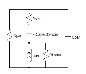
The actual equivalent circuit of most caps looks like this.

Keep this in mind when you only see C on the Logic Diagram.
Parallel caps of half the value and size in parallel makes the aspect ratio of L:W smaller which determines the inductance and raises the Self-Resonant-Frequency (SRF)
Although C/2 // C/2 is the same as C if they occupy the same area, the ESR is reduced in half which raises the Q and the maximum attenuation near SRF when the switching frequency is just below that.
Yet we know from physics and Saturn PCB design that the parasitic inductance is a ratio of length to width on a log scale. For SMDs mostly being 2:1 L:W ratio has a certain parasitic inductance. for the same multi-layer separation if it were 1:1 the inductance is reduced by almost 50% which raises the parallel self-resonant freq. (SRF) by almost 25%.
Thus putting more in parallel raises the bandwidth of the filter up to the SRF when designed properly.
These are common tradeoffs between cost, area, and critical attenuated required.

