0
\$\begingroup\$

A switching regulator (TPS63030) on my power management board is showing a weird problem after I opted to re-adjust the voltage output.

Note that this particular board has been used successfully in almost 2000 products.

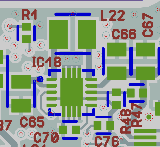
Recently, due to the ongoing chip shortage, I had to change some ICs (FPGA, memories etc.) and as per their requirement, I needed to change the output voltage of a couple of switching regulators. So, I asked my PCB manufacturer to swap the corresponding switching regulators' voltage-adjusting resistors on some boards already manufactured to make them compatible with the updated design. Since then, the switching regulators with updated resistors output weird voltages in almost 5 out of 10 PCBs. For example, for a particular regulator, the voltage that was supposed to go from 6V to 7V after this change is sometimes 2V, 4.5V, 6.2V or any other random value. See the snapshots of circuit and layout. R47 and R48 are the voltage-adjusting resistors in this example.

This is the circuit

enter image description here

Both regulators have similar circuit and layout (with different resistors values obviously,) and they are showing similar problems after the resistor change.

I have tried to resolve the issue by changing the resistor values, tolerances, etc. but to no avail.

\$\endgroup\$
10
  • \$\begingroup\$ This 4-switch circuit can either buck or boost the input voltage. Can you please tell us what is the input range and the expected output setting for the original design in which the IC did operate ok? Then, assuming the the input range is unchanged, what is the output setpoint with the ones showing weird outputs? Also, if you revert the components values back to the original selection, do weird boards now behave ok? \$\endgroup\$ Commented May 29, 2022 at 7:09
  • \$\begingroup\$ The input range is 4V-7.2V. The outputs were originally 3.8V and 6V which I want to change to 4V and 7V respectively. And no, when reverted back to the original configuration, they do not behave ok. The problem seems to appear only after re-work and doesn't go away after that but I can't think of a reason for it. \$\endgroup\$
    – Ahmed
    Commented May 29, 2022 at 7:23
  • \$\begingroup\$ @Ahmed Try reworking a board with the original configuration that has been confirmed to be working properly back into the original configuration. So basically remove the resistors, then put them back (or use fresh identical resistors)? \$\endgroup\$
    – DKNguyen
    Commented May 29, 2022 at 7:45
  • \$\begingroup\$ Can you measure voltage at the FB pin and confirm it is what the datasheet says (500mV)? If the value is correct, it means the regulator is working properly. In this case, I suspect solder flux residue across the 1MOhm resistor R47. If water-soluble flux was used, it can leave a conductive residue that has to be cleaned. You can also try to clean it and see if that changes the voltage. Or try lower resistance values, like 10k/1k instead of 1M/100K... \$\endgroup\$
    – bobflux
    Commented May 29, 2022 at 7:45
  • \$\begingroup\$ @DKNguyen I have done what you suggested several times. It does not help and I am unable to take the board back into original working condition no matter how many times I change the resistors. \$\endgroup\$
    – Ahmed
    Commented May 29, 2022 at 7:52

1 Answer 1

0
\$\begingroup\$

If your switching regulator is acting strangely, check to see whether it is oscillating at high frequency.

I've had experience of a TI part that had a great tendency to oscillate around 250 MHz; admittedly the PCB layout was sub-optimal (due to major space constraints) but we'd previously had no problems with a similar Linear Tech part.

\$\endgroup\$

Your Answer

By clicking “Post Your Answer”, you agree to our terms of service and acknowledge you have read our privacy policy.

Not the answer you're looking for? Browse other questions tagged or ask your own question.