2
\$\begingroup\$

I have a voltage regulator circuit which keeps failing. It is based around a switching regulator. It takes 14V input from a variable voltage regulator (lab setup) and outputs 5V. I see 14V on the input but 0V on the output.

Interestingly after I soldered this I checked the pads of the IC for shorts and I did not find any, but after powering everything I turned off the power and checked again and there were many shorts. I replaced the IC, and the same thing happened again. There must be something wrong with the circuit.

Particularly the voltage output to ground is showing just a few ohms.

Edit 1:

I have replaced the IC now twice. Each time I measure no shorts from the Vout to ground. As soon as I power the circuit once though, I measure shorts after powering down. Just powered for a few seconds. What could be happening?

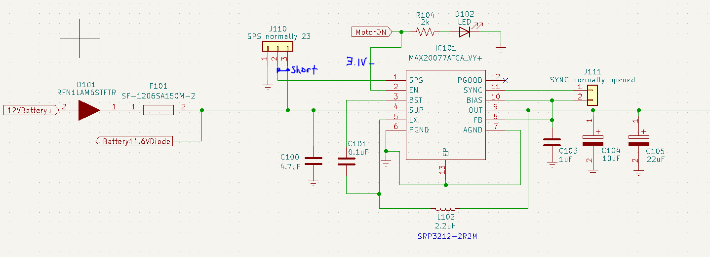
circuit

footprint

resistance check

\$\endgroup\$
13
  • \$\begingroup\$ If it's an automotive design then the MAX20077 will fail quite often due to automotive surges etc.. It's only got a max rating of 36 volts and this is weedy compared to what line surge voltages you can get in automotive. Ignore if not automotive but, you should definitely state where the input source of power comes from. \$\endgroup\$
    – Andy aka
    Commented Jan 21, 2023 at 17:27
  • \$\begingroup\$ Good point, let me update but right now I am testing with a variable voltage regulator so it should be a clean 14V. \$\endgroup\$
    – Feynman137
    Commented Jan 21, 2023 at 17:29
  • \$\begingroup\$ What wire length between power source and your circuit? Has it ever worked (this bit's important to know). Where does the MOTOR_ON signal come from and, what is it connected to? \$\endgroup\$
    – Andy aka
    Commented Jan 21, 2023 at 17:37
  • \$\begingroup\$ Minimal wire length I'd say 2ft. This is the first time I am trying this circuit, no it has never worked. The motorON signal comes from a multivibrator IC but I have verified that it is outputting 3.1V which is above the EN high threshold voltage. \$\endgroup\$
    – Feynman137
    Commented Jan 21, 2023 at 17:48
  • 1
    \$\begingroup\$ How does the oscillogram look like before it fails? What’s your inductor peak current rating? \$\endgroup\$
    – winny
    Commented Jan 21, 2023 at 17:56

1 Answer 1

3
\$\begingroup\$

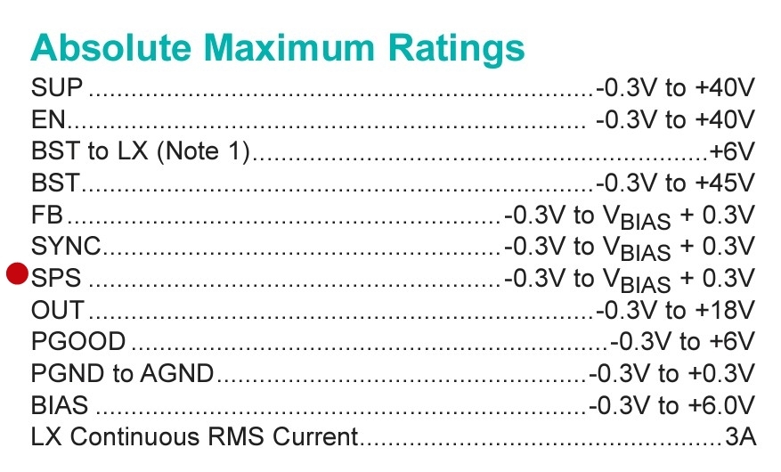
You cannot connect the SPS pin to the 14V input. This exceeds the absolute maximum of that pin: enter image description here

To enable spread spectrum you could connect SPS to BIAS. For testing you could leave it floating for now or connect it to GND.

Obviously, up until now the IC has been getting damaged at the first turn on after soldering a new IC. To make troubleshooting easier I recommended testing with a lower current limit on your lab power supply. Make it only slightly higher than the current draw you are expecting. Disconnect any loads on the regulator IC output for now if possible. A low current limit on the input voltage might prevent instant damage to the IC in case there are other issues at hand.

\$\endgroup\$
1
  • \$\begingroup\$ I rebuilt the circuit and made sure to never connect SPS to supply. In this case I am now seeing an output voltage from the circuit around 5V. But it becomes increasingly unstable as Vin increases. This is a separate question though so I will ask it in a another question. \$\endgroup\$
    – Feynman137
    Commented Jan 30, 2023 at 3:43

Your Answer

By clicking “Post Your Answer”, you agree to our terms of service and acknowledge you have read our privacy policy.

Not the answer you're looking for? Browse other questions tagged or ask your own question.