Termination resistors and why you need them
CAN and RS485 phsical layers use square pulses at high frequency to move data about - in fact the frequency of these pulses is high enough that you must consider the wires they travel upon as a transmission line. To borrow from the "water analogy" of electricity (pressure==voltage, flow==current) the transmission line effects of a water pipe can be seen when you have a water hammer occur: all the piping in the house shakes because the shockwaves travel through the piping (yes I know this isn't perfectly analogous, and yall have my apologies).
https://en.wikipedia.org/wiki/Transmission_line
Really every wire is a transmission line, however the effects only become important when the wavelength is close to the length of the wire or shorter. The heuristic rule is that if your wavelength is 10% of your wire length then you must start accounting for transmission line effects. Let's have a poke at some common CAN and RS485 wavelengths in typical twisted pair with a velocity factor of 0.65 and we will assume the fundamental frequency is half the data rate ie. a 1 bit followed by a 0 bit is one complete cycle:
\$\lambda=\frac{v}{f}, v=0.65*3.0*10^8\$
125kbit/s: 3120 meters
1Mbit/s: 390 meters
10Mbit/s: 39 meters
30Mbit/s: 13 meters
So given our 10% rule, we see that we're obligated to think about transmission lines anywhere between 39m and 312m with CAN busses and 1.3m to 3.9m with high speed 485 busses. This seems a little long compared to my real world CAN experiences, and probably the readers as well, so lets look at some of the disingenuous assumption of frequency tricked us with:
It is inappropriate to characterise the spectrum of these data signals by their data rate alone; these aren't sine waves, they're sharp edged square waves. A better number is to use the \$BW=\frac{0.35}{Rise Time}\$ rule-o-thumb (good ref here: https://www.edn.com/rule-of-thumb-1-bandwidth-of-a-signal-from-its-rise-time/). Now whats the rise time? CAN is slow and defines a sampling time well towards the end of the bit period:

UART signals like RS485 are sampled differently, and this is a bit of a gap in my knowledge - I know common UART implementations use 16x oversampling to determine the bit value and recover the clock phase (and rate?), though I'm unaware of universal timing requirements or rules of thumb so I go by 1/10th the bit period as a MAXIMUM rise time, and I try to achieve this for CAN as well.
This means our peak frequencies are closer to:
\$f=\frac{.35}{\frac{1}{10*Rate}}\$
So 125kbit/s is now 437kHz, of which 10% wavelength is 44.6m, 7 times shorter than the naive assumption.
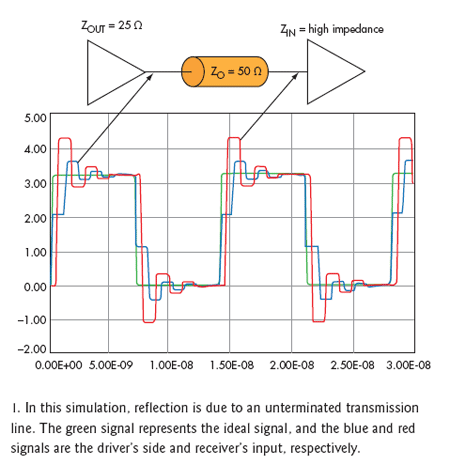
What do termination resistors do? Termination resistors absorb the stored energy in the transmission line. A termination resistor matched to the transmission line's characteristic impedance will absorb every last drop without reflecting any energy. When there's no reflections the voltage measured at any point along the transmission line is the voltage the transmitter intended to send. In the presence of reflections, the voltage at any point will be the sum of the transmitted wave and the reflected wave; here's a great picture of what that looks like (from a previous SE-EE post: RS485 Cable Lengths and Reflections):

You can see that the nice flat square wave levels have been replaced by ringing as the reflected waveform bounces back and forth along the line.
CAN Bus specifically
CAN bus has it's own issues compared to RS485 (or ethernet or RS232) in that the recessive state of the bus is not driven by the transceivers. This choice was made so that if two nodes began to transmit on the bus, one node could win arbitration by driving a dominant state while the other reuested a recessive state - both transceivers monitor the bus and if the recessive request is overruled the losing node will back off. The implementation of this is shown here in an LTC2875 datasheet snip:

CANH can be pulled high and CANL can be pulled low to indicate the dominant state, but the termination resistor load on the bus must bring the differential bus voltage low enough to become the recessive state. With no or negligable load on the bus the voltage cannot relax fast enough to trigger the recessive state and all recevier nodes plus the transmitter node will flag an error, and eventually all transmitters will go BUS OFF as they continue to lose arbitration or detect form errors.
But one time my friend made it work with no resistors, this is all wrong!
This analysis neglects things like receiver load, which could satiate a low speed CAN bus' requirement for some pulldown. Not everything here is perfect, but it's a good start, and a great reason to use termination resistors, and at no point has the number of devices come into play.
dangling refs
https://en.wikipedia.org/wiki/CAN_bus#Bit_timing
https://www.analog.com/en/products/ltc2875.html


