2
\$\begingroup\$

Consider this arrangement of a radio, a long coax cable, a small length of "random" cable and an antenna. The radio, the coax and the antenna all have the same impedance, but the random cable is impedance mismatched.

How this short length of impedance mismatch may affect the radio performance?

Does the rule of "smaller than 1/10 wavelength" apply to this short stub of random cable making this mismatch irrelevant?

\$\endgroup\$
4
  • 2
    \$\begingroup\$ A random cable may be mismatched but, if only a few percent then it's hardly a problem even for a full wavelength of cable. The effect is all easily simulated using free tools and a little patience. You will learn such a lot by varying lengths and impedance values using a simulator like micro-cap. \$\endgroup\$
    – Andy aka
    Commented Jul 16, 2022 at 19:30
  • \$\begingroup\$ Yes, but whether it matters depends on the system susceptibility to mismatch, the length of the mismatch (even if significantly smaller than \$\lambda\$), and the severity of the mismatch. Now would be a good time to whip out a Smith chart or find an online impedance calculator and work out a few examples -- or learn how to use a Smith chart and expand your RF design knowledge. \$\endgroup\$
    – TimWescott
    Commented Jul 16, 2022 at 20:33
  • 1
    \$\begingroup\$ That's not at all clear - the directions of the fields must change radically in the joint. If you are far away from the frequency range of higher waveforms than TEM you can well assume the effect can be handled as an impedance mismatch. Simulate the effect for ex. with Micro-Cap, which has an easy to use TEM waveform transmission line. \$\endgroup\$
    – user136077
    Commented Jul 16, 2022 at 20:37
  • \$\begingroup\$ You should try to evaluate the Zo impedance of your twisted wires which can be between 70 and 120 Ohm. Search for AppCAD from Avago Technologies. \$\endgroup\$
    – Antonio51
    Commented Jul 16, 2022 at 21:49

3 Answers 3

1
\$\begingroup\$
  • let me give some wider bandwidth answer without all the math.

Imagine, if you will, that you can see "any" mismatch with a Time Domain Reflectometer (TDR) within a defined SNR range. So even short reflections can be seen over a long matched cable. You understand these reflections add or subtract noise on the signal by under or over the nominal impedance and long delays with possible small mismatches at either end repeating themselves. This can be measured by SNR or distortion levels or even phase noise in dB down from the carrier.

The 10% wavelength rule of thumb is based on a breakpoint in percentage of the worst attenuation of carrier loss due to mismatched short feeders. 5% is a better quality standard for narrow band RF.

But for baseband or extreme wideband Network Analyzers that Rule of Thumb gets reduced significantly both on length and tolerance of mismatch for SNR reasons. A short mismatched feed on signal or ground will have significant quality effects on baseband signals for measurement errors or or if you expect high SNR quality such as baseband broadcast video with ghosting effects.

So the BW expectations of the channel must be much higher than the signal for wideband high SNR signals. This is not necessarily true for Logic Signals except near the transition with high gain. This is when signal integrity matters with digital crosstalk on analog signals, it is best to use twisted pair magnet wire if coax is not possible in order to prevent loose jumpers on breadboards wreaking havoc to lower the impedance and possible add a source R to match the link to at least prevent reflections at the source even if the load is mismatched open circuit in logic.
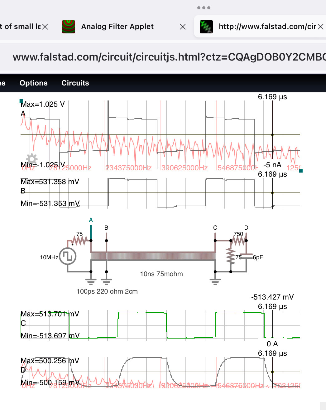
enter image description here

For tolerable losses the breakpoint in narrow band carrier signals is 10% wavelength.

Time domain & FFT Simulation

A 10 ps sample time was used to plot the red log. spectrum of from 10 MHz to 1 GHz and there is signal over this entire range with some dB level down.

Observation

So the 100 ps 3cm twisted pair wire (220 ohm ) visibly gave "good square results" at the end of the long line, but not perfect. Imagine how bad it would look it it was inductive only with very high impedance yet still only a short wire delay! It took a low pass filter on D to restore the peak to peak expected Voltage of 1vpp or in other words, reduce the wideband receiver to match the channel (Ideal Receiver theory) of the signal fundamental due to a tiny mismatched jumper wire.

Here is the frequency domain of the same

Notice the 100 ps is the inverse of f=10GHz and the attentuation goes from 6 to 6.6 dB at 5% f.
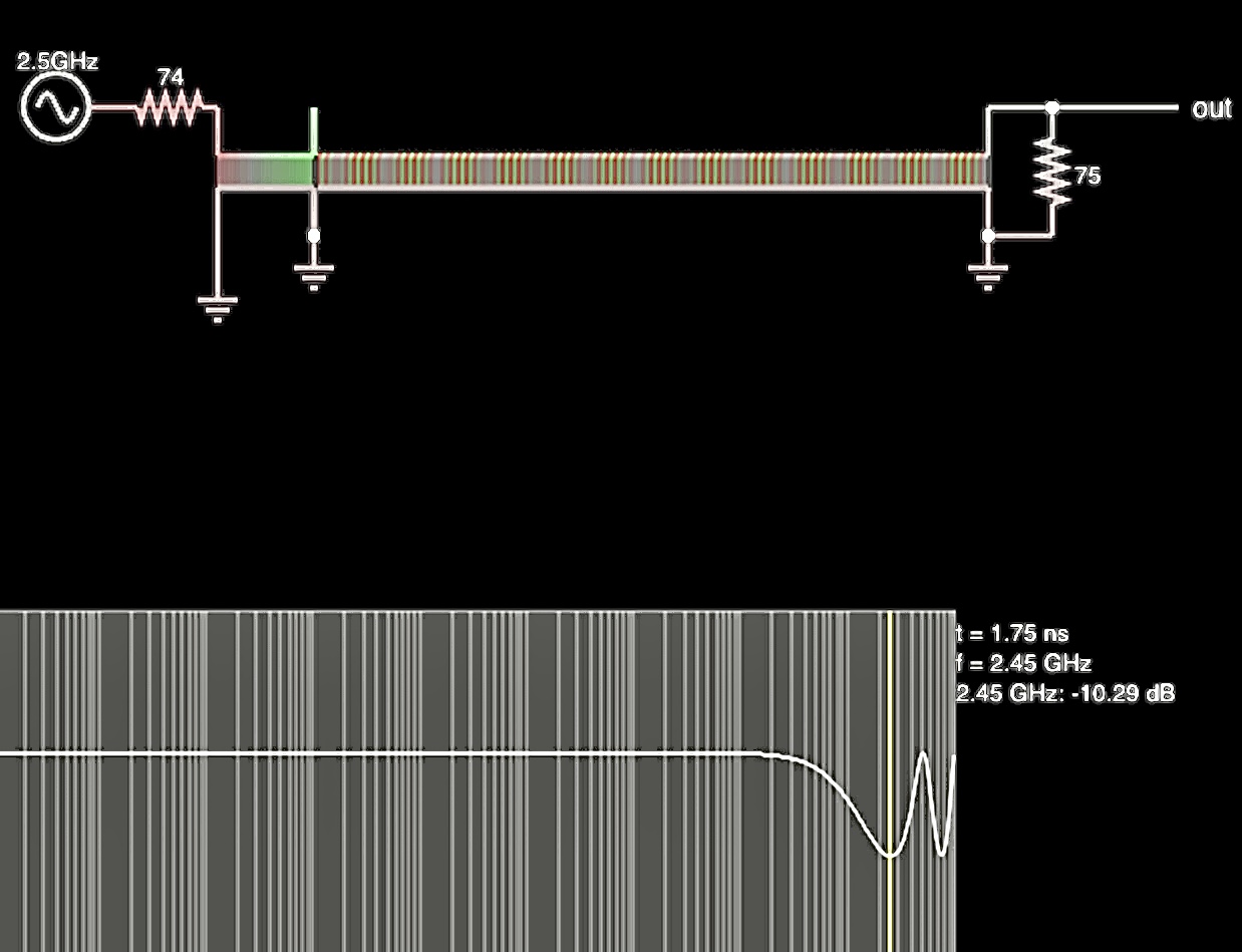
enter image description here

\$\endgroup\$
1
\$\begingroup\$

Other answers have focused on the impedance mismatch issue. I would like to point out another issue arising from joining a coaxial cable directly to a twisted pair (with no balun). That issue is mode conversion. Mode conversion is the generation of a common mode signal from a differential mode signal or vice versa. Mode conversion occurs when the is an change in the "unbalance factor" in the circuit (in the absence of a balun of some sort.) The unbalance factor for coax is ideally near 1. The unbalance factor for twisted pair is ideally near 0. Common mode signals in an antenna feed-line are problematic because they cause the signal to radiate from the feed-line. If the antenna is used for reception, this feedline radiation will cause attenuation of the signal seen by the receiver. If the antenna is used for transmission, this radiation will alter the overall radiation pattern, perhaps radiating in directions that are unwanted, and reducing the power radiated in the directions for which the antenna was designed.

To sum up, you should use a balun if you wish to attach a coax cable to an antenna or to a twisted pair cable even if the coax and twisted pair have the same characteristic impedance. You should not have a true balun when connecting a twisted pair to a center-fed antenna. A true balun matches two devices with different unbalance factors, (and possibly also matches impedances.) You might use something that might be colloquially called a balun to connect a twisted pair to an antenna, but it should only be an impedance matching device/network, not a true "balun".

\$\endgroup\$
1
\$\begingroup\$

Does the rule of "smaller than 1/10 wavelength" apply to this short stub of random cable making this mismatch irrelevant?

At what frequency?
As already pointed out, and ...
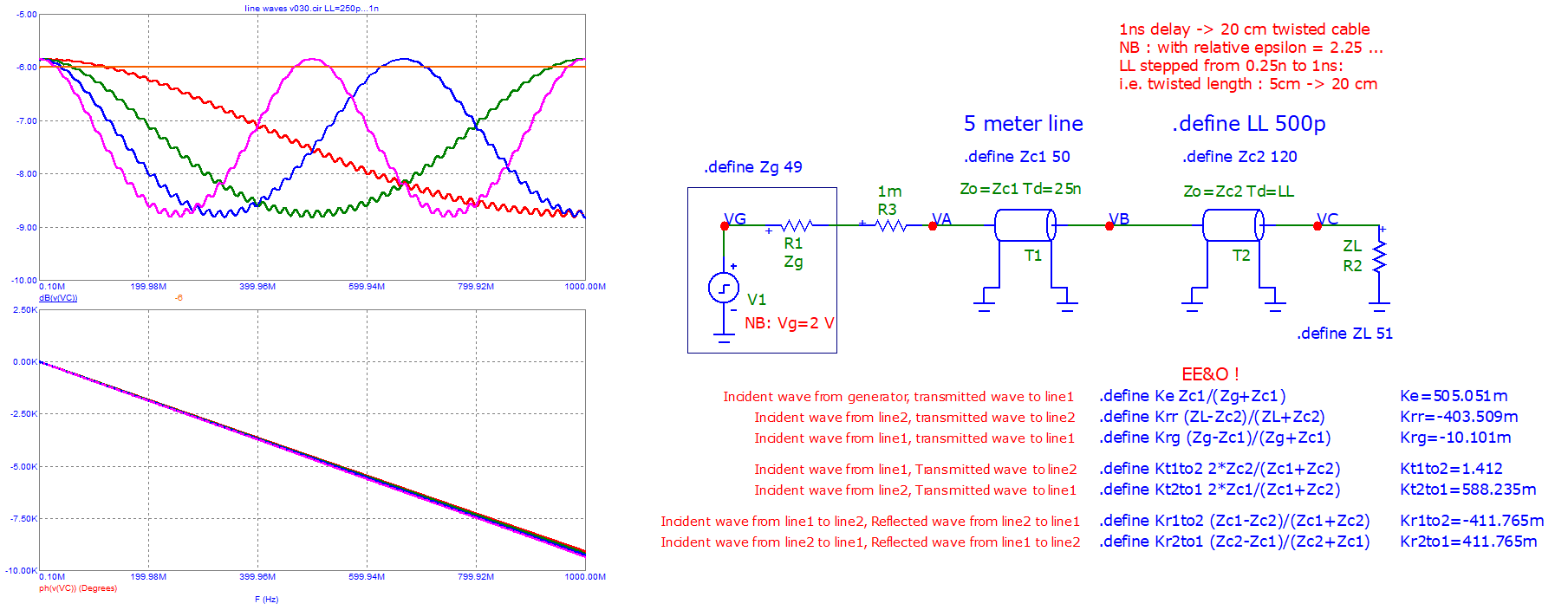
with some other data, one can make this simulation, and see the effect of a "twisted line" ...
equivalent length from 5cm to 20 cm ...

One can see the losses (theoretical -6 dB) from QUASI matched lines, variable with the frequency.
Losses should be (in this case) between -6 dB to -9 dB, so a maximum of 3 dB added losses.

enter image description here

As already pointed out, the output pulse is "undistorted" and "good" for use by other devices wired at point C ... but not at point A (one pulse is negative (?) ... and there is another positive that can create "garbage" ... with very "fast" devices (cases where the twisted line can be considered as an added "capacitor" or "inductor" or both).

enter image description here

\$\endgroup\$

Your Answer

By clicking “Post Your Answer”, you agree to our terms of service and acknowledge you have read our privacy policy.

Not the answer you're looking for? Browse other questions tagged or ask your own question.