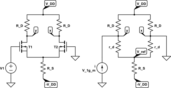
I am confused regarding the analysis of the circuit on the left and its small-signal equivalent circuit on the right:

simulate this circuit – Schematic created using CircuitLab
Here is my analysis:
Let \$i_1\$ and \$i_2\$ be the current through the parts above and below node \$y\$ respectively. Given that node \$x\$ is grounded, and assuming the reference \$V_{\text{ref}}\$ is at ground potential, we have:
$$i_1 = g_m \cdot \frac{r_d}{2R_D + r_d} \cdot V_1$$ $$i_2 = g_m \cdot \frac{2R_D}{2R_D + r_d} \cdot V_1$$ $$V_y = i_2r_d = g_m \cdot \frac{2R_Dr_d}{2R_D + r_d} \cdot V_1$$
However, \$V_y\$ is given as:
$$V_y = g_m \cdot \frac{R_Dr_d}{R_D + r_d} \cdot V_1$$
Where did I go wrong?
For clarity, \$i_1\$ is the current through the left \$R_D\$ and \$i_2\$ is the current through the left \$r_d\$.
