0
\$\begingroup\$

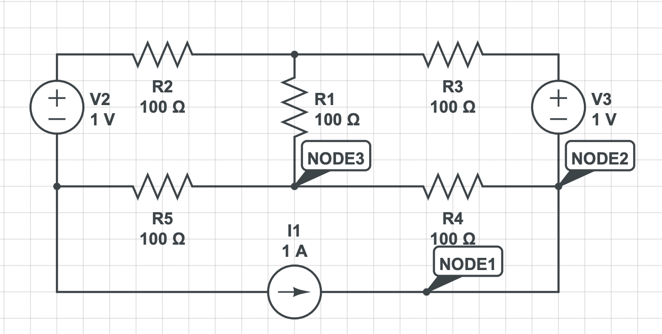
Lets say I have this circuit below and I want to solve it using the Mesh Method.

enter image description here

For every essential loop I define the current loops \$i_a\$ (left), \$i_b\$ (right), and \$i_c\$ (below) clockwise. The mesh equations are:

$$-V_2 + R_2i_a + R_1(i_a-i_b) + R_5(i_a-i_c) = 0$$ $$V_3 + R_4(i_b-i_c) + R_1(i_b-i_a) + R_3i_b = 0$$ $$i_c = -I_1 = -1$$

When it comes to the \$i_c\$ loop I know that \$I = -1\$, but how is it true that the whole \$i_c = -1\$? Isn't the current splitting at node 2?

Why is it true that the current passing through the wires conflicting with the opposing effect of loops \$i_a\$ and \$i_b\$ are exactly -1 A?

It is not intuitive to me why it is the case and/or if it is always the case. It is really bugging me.

\$\endgroup\$
4
  • \$\begingroup\$ I agree with user287001, I don't understand how you have arrived at \$i_C=-4A \$. You're right to ask why \$i_C=-4A \$ because it isn't. \$i_C=-1A\$, or maybe 1A \$\endgroup\$ Commented Aug 19, 2022 at 20:07
  • \$\begingroup\$ I'm sorry. It is now corrected. \$\endgroup\$
    – ludicrous
    Commented Aug 19, 2022 at 20:07
  • 1
    \$\begingroup\$ \$I_{R4} \ne i_{c}\$. \$\endgroup\$
    – user319836
    Commented Aug 19, 2022 at 20:14
  • 1
    \$\begingroup\$ You have indicated that the mesh currents are clockwise. Could you please complete the labeling the directions for the currents and voltages through and across the individual components? Thanks. \$\endgroup\$
    – user319836
    Commented Aug 19, 2022 at 20:45

2 Answers 2

1
\$\begingroup\$

It has to do with superposition, which is the mathematical "engine" under the hood of loop analysis. The resistor doesn't care where the each individual electron moving through it comes from, it will develop the same voltage at its terminals in accordance with Ohm's Law. The contributions also stack, so the effect of one current loop in isolation can be added to the effect of another current loop that happens to pass through the same device to come to the correct answer.

\$\endgroup\$
0
\$\begingroup\$

Think about how that would show up in the equations. The current through R4 (right-to-left) isn't just \$-i_c\$, it's \$i_b - i_c\$. And the current through V3 (top-to-bottom) is \$i_b\$. So the equations do allow for the current to split or merge at node 2, according to the value of \$i_b\$.

Or in other words, \$-i_b\$ is the amount of current that doesn't go through R4, and goes the long-way around the right-hand loop instead. (Then some of that current may be diverted away from R1 by \$-i_a\$)

\$\endgroup\$
4
  • 1
    \$\begingroup\$ The OP defined the mesh currents to be clockwise. So \$I_{R4} = i_{c}-i_{b}\$ \$\endgroup\$
    – user319836
    Commented Aug 19, 2022 at 20:26
  • \$\begingroup\$ The mesh currents are \$i_{a}\$, \$i_{b}\$ and \$i_{c}\$. \$I_{R4}\$ is not a mesh current, but its direction is defined by them according to the constraints of the problem. \$\endgroup\$
    – user319836
    Commented Aug 19, 2022 at 20:32
  • \$\begingroup\$ @RussellH previous version of this answer still had \$I_{R4}\$ in the wrong direction as defined in the answer \$\endgroup\$ Commented Aug 19, 2022 at 20:35
  • \$\begingroup\$ What is missing is a "labeled" diagram. What is to be considered the direction of current and or voltage drops is missing in the original posting. It is somewhat arbitrary. It appears that you and I chose differently I am out of time right now but I will submit an answer later from my point of view. Stay tuned \$\endgroup\$
    – user319836
    Commented Aug 19, 2022 at 20:42

Your Answer

By clicking “Post Your Answer”, you agree to our terms of service and acknowledge you have read our privacy policy.

Not the answer you're looking for? Browse other questions tagged or ask your own question.