1
\$\begingroup\$

I have a 400V three-phase [TT system][1] that I use for my company in Italy. I was wondering if there is a direct way to detect the phase number at any point in the wiring.

I have the phases numbered at the meter as L1, L2, L3. What I'd like to do is to test a random line in the downstream wiring and detect if it's L1, L2 or L3.

I have a phase rotation meter and I know that I can test if the rotation is correct at any point (it is, since everything works as it should), but as far as I know the phase rotation can be correct even if the phases are i.e. in the sequence L3, L1, L2. I'd like to know if that's the case at any point in the wiring.

The reasoning behind this test is that I have a solar array which is unbalanced on the three phases. I want to move some of the single phase loads where I have more solar power, to avoid sourcing power from the grid when I have it available on other phases of my solar array. A second minor reason is to have consistent wiring colors everywhere, to avoid running in the same issue in the future.

I can figure out what I need to know with a bit of indirect tests, but I was wondering if there is a clever or faster way to test it directly on the wire. [1]: https://en.wikipedia.org/wiki/Earthing_system#TT_network

\$\endgroup\$
2
  • \$\begingroup\$ Can you safely isolate from the power while you work it out? If so, you have lots of options, including specialist tools (VCI3 cable and phase indicator is the first I found while searching). If not, load one of the phases and use watch which meter spins (or any other method to sense current). \$\endgroup\$
    – jonathanjo
    Commented Oct 4, 2022 at 12:53
  • \$\begingroup\$ Safety first. You can use a HF "power" wave "superposed" on one line (active or not) and detect it anywhere. But this can be "difficult" when "many" wires distribution ... Always use same color for same phase line. \$\endgroup\$
    – Antonio51
    Commented Oct 4, 2022 at 14:42

3 Answers 3

1
\$\begingroup\$

I was wondering if there is a clever or faster way to test it directly on the wire

Unfortunately not. If you have lost track of which wire is which then you could disconnect all power lines from the incoming AC and short that particular line to neutral. Then head back to the other end of the cable and locate which wire is shorted to neutral using a continuity meter.

\$\endgroup\$
0
\$\begingroup\$

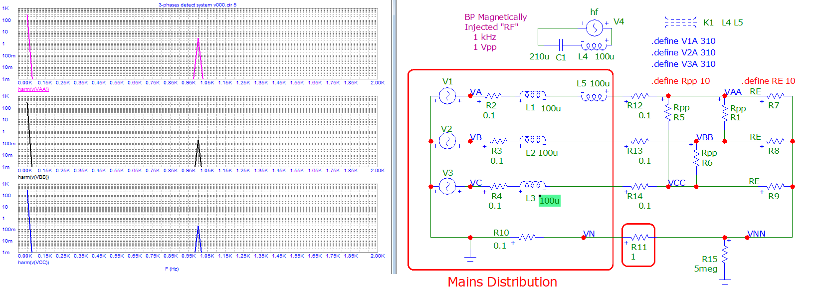
This can help you develop a "sense" system.

Simulated with "heavy" loads (resistive only) (triangle and star wired).

enter image description here

\$\endgroup\$
0
\$\begingroup\$

a clever or faster way to test it directly on the wire

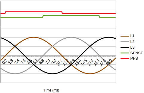
At 50 Hz the period is obviously 20 ms with 6.6 ms lag for each phase (or 60 Hz: 16.7 ms period, 5.6 ms lag).

How about

  • A GPS receiver with 1 PPS output (accuracy might be as good as 4 ns)
  • Any simple sensor on the wire, looking at the rectified signal
  • An oscilloscope or a microcontroller

Measure from the rising edge of the PPS (red) to the rising edge of the SENSE (green) do this at the meter to find out the phase of the electricity against absolute time, then do it on your unknown cable.

enter image description here

Make sure you measure the frequency! Some electricity suppliers have quite large adjustments: in the Netherlands it's supposedly 10 mHz. See experiment and also some experiments in the US.

AtMega have a nice application note on zero-crossing detection with very low hardware.

Also some optocouplers are specifically designed or this, eg MID400, which while "slow" (1 ms), perfectly good for this.

\$\endgroup\$

Your Answer

By clicking “Post Your Answer”, you agree to our terms of service and acknowledge you have read our privacy policy.

Not the answer you're looking for? Browse other questions tagged or ask your own question.