Any insight would be greatly appreciated.
Any feedback system that performs "regulation" compares its output with a known fixed value and, attempts to minimize the errors. Thus the output becomes the same (or a fixed ratio) to the known fixed value (aka the demand) thus: -
Output equals demand
That's the simple theory but, to drive the output towards the demand requires an error and, what you are trying to do ideally is minimize the error. Do you see the problem?
You cannot have infinite gain and so, you accept that have sufficient gain to create a steady-state error in the output that is acceptable i.e. it doesn't precisely cause output to equal demand but, we "live with" the error.
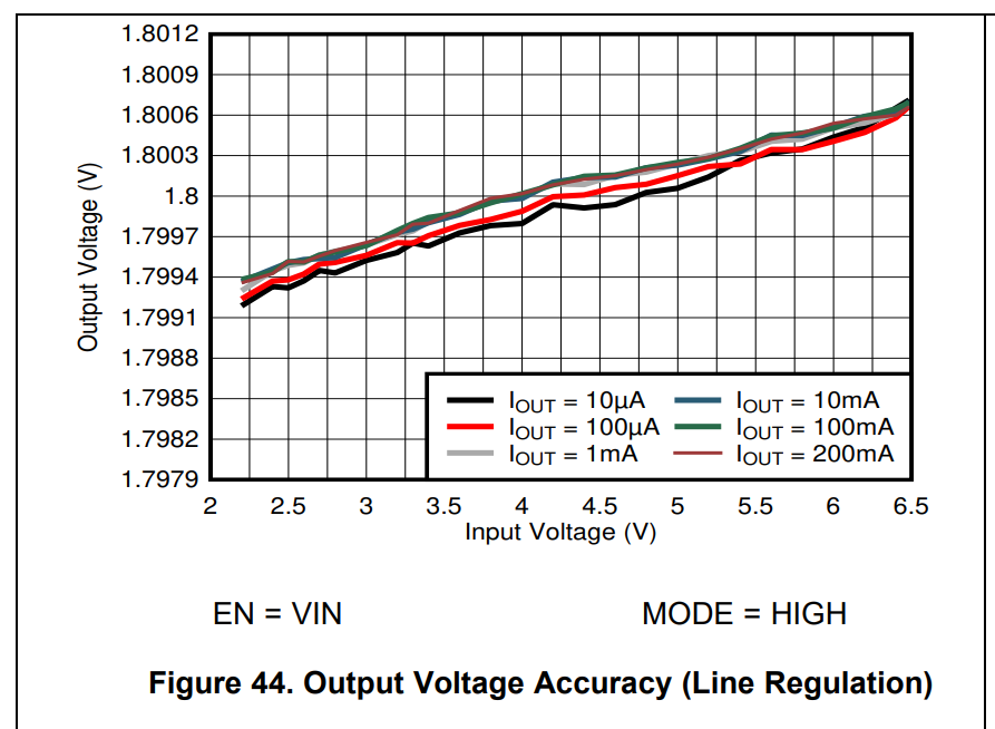
If you look at your figure 4 (in the question) you could work how much the error amplification is. For an input range of 2.5 to 6.5 volts (4 volts delta), the output shifts from 1.7994 volts to 1.8006 volts (a delta of 1.2 mV). Thus, you can say that the error amplifier has a net gain of 4 volts ÷ 1.2 mV i.e. 3333.33.
There are more complexities to this but that's a broad estimation of the DC error gain.
Then there are dynamics to consider; if the input voltage has a lot of ripple voltage on it, the error amplifier gain is inevitably smaller (think of the open loop gain of an op-amp and how it starts falling above a few hertz). So when you say this....
Shouldn't the feedback be able to perfectly compensate for the change
the input voltage by adjusting the duty cycle?
....There are things to consider.
- The first is that any input change won't drive the error amplifier to produce a steady-state error immediately because of the limited dynamics of the error amplifier.
- The second thing to consider is that a switching regulator is fundamentally delayed by up to one switching cycle. In other words it can't begin compensation immediately. This of course can cause a significant disturbance in the output if the error amplifier is not "well-tempered" and the input disturbance is profound.
- The third thing to consider in a switching regulator is that there is an enormous phase shift caused by the LC circuits (used to transfer energy). The phase shift is 180° and occurs in a very small part of the spectrum. This plays havoc with error amplifiers and, considerable efforts have to be made to "compensate" the error amplifier to prevent a nice voltage regulator turning into an oscillating chip fryer. This phase change could, turn negative feedback into positive feedback.
So, in the real world, the error amplifier becomes severely hampered. To help it we use input and output capacitors to stop things moving too fast and, sometimes we use feed-forward. Feed-forward of the input supply voltage can result in a direct change of the duty cycle in some regulators so that the "error control system" is given a head-start and doesn't have to work so hard.
It's a tricky old business given also that regulators have a very wide load current that throws a big spanner in the works regarding the error amplifier.

