2
\$\begingroup\$

After doing a bunch of research on this, I'm still confused on whether I need a driver circuit for a P-channel MOSFET if the MOSFET is only switching a device at the same voltage level as the controller.

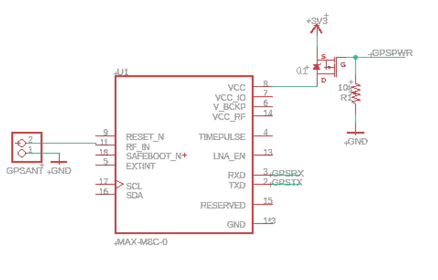
I need to switch on and off a GPS module through a 3.3 V logic IC. This is my current circuit:

enter image description here

The MOSFET is a DMG3415U-7.

Is this the right circuit for this use case? I've seen many people discussing an issue where in certain cases the source voltage could be fed into the microcontroller, damaging it. Would that be an issue when the source voltage is 3.3 V?

\$\endgroup\$
2
  • 2
    \$\begingroup\$ How are all of the other module pins connected when you want to remove power to the module? This matters very much. \$\endgroup\$ Commented Nov 21, 2022 at 21:03
  • \$\begingroup\$ @ElliotAlderson all of the GNDs will be connected through a pour. UART will be connected. \$\endgroup\$
    – Vera Fodor
    Commented Nov 21, 2022 at 22:00

1 Answer 1

3
\$\begingroup\$

This circuit will provide +3.3 volts to VCC whenever GPSPWR is low, meaning that your VCC power will be present when GPSPWR is disconnected. When GPSPWR is high enough to be near Vgs(th), or about +3 volts worst case, Q1 will start to switch off, leaving VCC floating. Per the data sheet, GPSPWR could could go as high as 8 volts above your 3.3 volt rail (11.3 volts) and Q1 will safely remain "off." Similarly, GPSPWR could be 8 volts below VCC (-4.7 volts) and Q1 will be on with only 3.3 volts on the drain.

GPSPWR thus has inverse logic, and with a minimum Vgs(th) of 0.3 volts, you must get it really close to your 3.3 volt supply to turn power off. Adding an N-channel FET drive with a pull-up gives you non-inverted logic. In either case, you need to remember that the VGS(th) of the gate attached to GPSPWR sets your logic threshold, so choose a FET that switches at the voltage which is appropriate for your logic level.

\$\endgroup\$
3
  • 1
    \$\begingroup\$ It would probably be better to put the resistor R1 from gate to source, so OFF by default. \$\endgroup\$
    – PStechPaul
    Commented Nov 22, 2022 at 0:19
  • \$\begingroup\$ Wouldn't the MOSFET be normally nonconductive when GPSPWR is disconnected? The MOSFET is enhancement-type. Am I confusing the types of MOSFETs? \$\endgroup\$
    – Vera Fodor
    Commented Nov 22, 2022 at 0:20
  • 2
    \$\begingroup\$ No, it is OFF when gate to source is below Vgs(th), so that is where the resistor should be if that's what you want. \$\endgroup\$
    – PStechPaul
    Commented Nov 22, 2022 at 1:20

Your Answer

By clicking “Post Your Answer”, you agree to our terms of service and acknowledge you have read our privacy policy.

Not the answer you're looking for? Browse other questions tagged or ask your own question.