0
\$\begingroup\$

I have a 3 * 600W LED drivers for running my house lighting. Due to inrush current I can't have them all turn on at the same time without it tripping the MCB.

The transformers have a remote control circuit, 3 wires, 5V. GND and RC:

Power on : "High" >2 ~ 5V or Open circuit Power off : "Low" <0 ~ 0.5V or Short circuit

The 5V line on each transformer powers up straight

I have this working fine with an Arduino Nano having a 5/10/15 second delay (staggered for each transformer) and then going high on a pin... but it feels like using a sledgehammer to crack a nut.

I'd like to replace it with something a little simpler - my rough thought is that a couple of resistors a and a capacitor would probably solve this, but I'm not good at this end of electronics - any help in designing this circuit is much appreciated.

I think R1 goes from Vcc to C1, and R1 and C1 are sized to take at least n seconds from fully off to triggering the on state.

I am also pretty sure there needs to be another resistor, R2, which will drain C1 to ground when Vcc is turned off (so that long before the capacitors inside the PSU drain, C1 will be at 0V so the delayed start will apply when power is returned)

Note this is lighting for the house so these PSU's should be always one - this is just so they behave sensibly if for any reason power is cut to that circuit and then comes back.

For reference: datasheet: https://www.meanwell.co.uk/assets/pdf/HLG-600H-spec.pdf

\$\endgroup\$
1
  • \$\begingroup\$ power often cuts out for 2 seconds or 10 seconds when lightening or a squirrel gets involved; that indicated a micro might be a better and simpler choice than a naïve analog device. \$\endgroup\$
    – dandavis
    Commented Dec 12, 2022 at 21:43

3 Answers 3

3
\$\begingroup\$

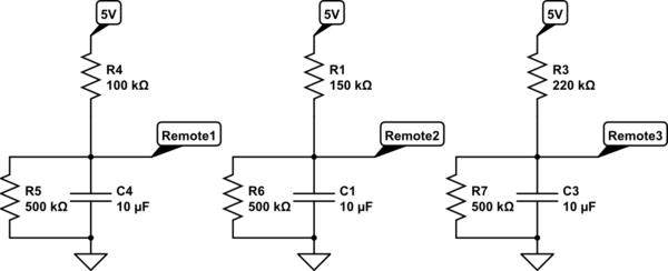
If you are tripping your main circuit breaker when turning on three simultaneously, then it's probably related to inrush current. You could try to limit that, but it's a little more work. Also, inrush current is usually pretty short, so you probably don't need 5 second delays between them. One second will most likely be sufficient. To get you a circuit that delays at power on is easy. Just use an RC. You can use 2.2RC (since it turns on between 2V-5V). If it took until 5V to turn on, then use the full cap charge equation 5RC.

schematic

simulate this circuit – Schematic created using CircuitLab

The 500k will discharge the cap when the power is off. The trick is what to do if power is removed for a short period of time and then comes back. For that we'd need to add some transistors that're controlled by a similar RC to keep them on at first but then turn off so that the RC can charge and turn on the lights.

In my opinion once you start adding the transistors, you might as well use the Arduino. Since this is a home project, not made for mass production, the Arduino gets you past your hurdle for not much money.

\$\endgroup\$
0
1
\$\begingroup\$

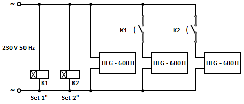
Two 'off-the-shelf', 'on-delay' timers, with adequate contact rating, would do.

enter image description here

\$\endgroup\$
0
\$\begingroup\$

Well, you could just use RC's to time the circuit, but this also has problems associated with it as if there are 'brownouts' then the capacitors are already charged and it won't come up in sequence. So RC's are simpler but not a great way to accomplish reliable sequencing.

One thing you could do is use RC's with a voltage regulator with a undervoltage lockout. If the power does go down, maybe have an RC on the UVLO that can keep it low for X seconds.

\$\endgroup\$

Your Answer

By clicking “Post Your Answer”, you agree to our terms of service and acknowledge you have read our privacy policy.

Not the answer you're looking for? Browse other questions tagged or ask your own question.