Drawing current from a reference chip is usually not good for accuracy:
It'll heat the chip so it will drift.
Any resistance in series with the output will drop voltage. The largest resistance in the circuit will probably be the chip's bondwires, unless it is countered by the chip having separate output and feedback pins and sensing voltage at the point of use and not at the output on the chip.
Drawing AC, pulsed, or any current that is not constant DC also brings the problem of non-zero output impedance, transient response, and settling time.
So if you need to draw current from a reference, it can be a good idea to use a buffer even if the current is within the capabilities of the reference.
However if you want to make a high current precision DC buffer, you'll have the same problem with wire impedance dropping voltage with current, so if you want accurate voltage at the load you'll have to use 4-wire "Kelvin" connection. This has the advantage of compensating for the ammeter resistance if you put one in series with the output, too.
On a printed circuit board, both the load seen by the buffer and the length of these traces is fixed in the design, but on a bench with wires it is not, so the circuit has to be stable with various lengths of wires, which means a wide range of inductance and parasitics, and various loads (C, L, R...).
It's a feedback system with part of the feedback network being external (wires + load interaction) therefore its stability will depend on phase shift introduced by all these things, which can vary. It should be designed conservatively to still be stable over a wide range of loads and wire lengths, which means it can't be optimized to be fast, or have a fast transient response. Fast needs low and known phase shift at high-ish frequency to implement a stable system.
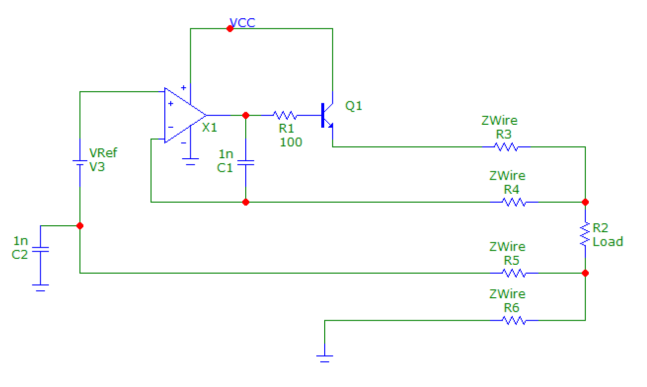
One possible implementation is this (simplified schematic):

The load's positive terminal is sensed with a wire carrying no current, and the load's negative terminal is used as ground for the reference. Both of these combined compensate for resistance in the current carrying wires.
However the extra inductance means you'll probably have to include compensation capacitors C1,C2 to give it a known stable behavior at high frequency, possibly a snubber in the output too.
First, in Digi-Key, for "Amplifier Type", I select: Buffer
Usually the "buffer" category is about opamps with an internal feedback network that maeks them unity gain, so the feedback pins are not exposed, so that's not what you need, wrong product category. These tend to be fast buffers because one reason to put the feedback network inside the opamp is to reduce HF parasitics, and there's no point to do it at low frequency.
Anyway, opamp shopping criteria:
For good DC accuracy, you need low offset and drift. For best performance, you can use a chopper "zero drift" opamp, at the cost of speed and a bit of HF noise. A "precision" opamp without chopper may offer higher speed and lower HF noise, but since it isn't a chopper, it won't have zero drift or near zero offset. It's possible to combine a slow chopper opamp and a fast one to make a fast zero-drift opamp, but the 4-terminal measurement and variable length wires mean you don't need fast.
High open loop gain to have lots of feedback at DC is also necessary to compensate for voltage drops.
Gain-bandwidth isn't very important for DC precision, maybe a few MHz is enough. It depends on how much compensation you use. Compensation makes the circuit more stable and slower, so there is no point in buying a more expensive, fast high performance opamp to then slow it down so it doesn't oscillate with 1 meter long sense wires.
Voltage feedback opamps offer much less offset and drift, so you can uncheck "current feedback".
Rail to rail is not necessary if you plan for 6V, any opamp with say 9V supply can output enough voltage into the base of the BJT to make it output 6V.
Opamp PSRR does matter, but you have to look at the PSRR plot across frequency, not just the single number in the datasheet tables. Another option is to use a clean power supply.
Also it would be a good idea to add overcurrent protection to protect the transistor.
However, if you want to experiment, you can just use something cheap. Preferably with the same gain bandwidth product as the zero-drift opamp you'll use in the final product.

