4
\$\begingroup\$

As a homework assignment, I was given to design a simple vending machine circuit as follows

  • Receives 5 cent, and 10 cent one at at time.
  • 20 cent per snack, gives change when necessary (IE, 25 cents, gives 5 cents back with a snack)
  • Once snack is given, it goes back to it's original state.
  • Requires asynchronous reset. Resets at active low (back to initial state), and forces to give out any change. At active high, operates normally.
  • 3 Inputs (D, N, R) 2 outputs (Snack, Change)
  • DN (00) specifies no coins, (01) specifies a nickel and (11) specifies a dime

I have completed everything from state tables to drawings but it's VERY complicated and I don't think this is the best way of doing it. Here's what I did

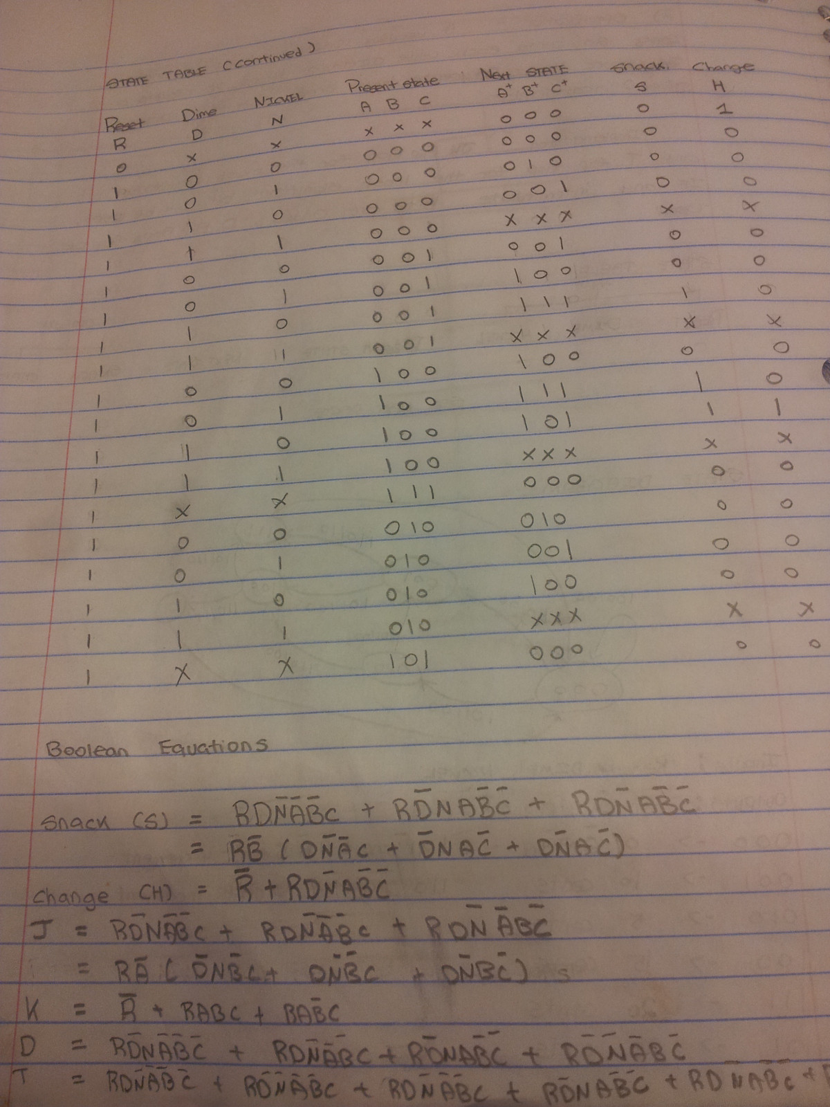
State Diagram enter image description here
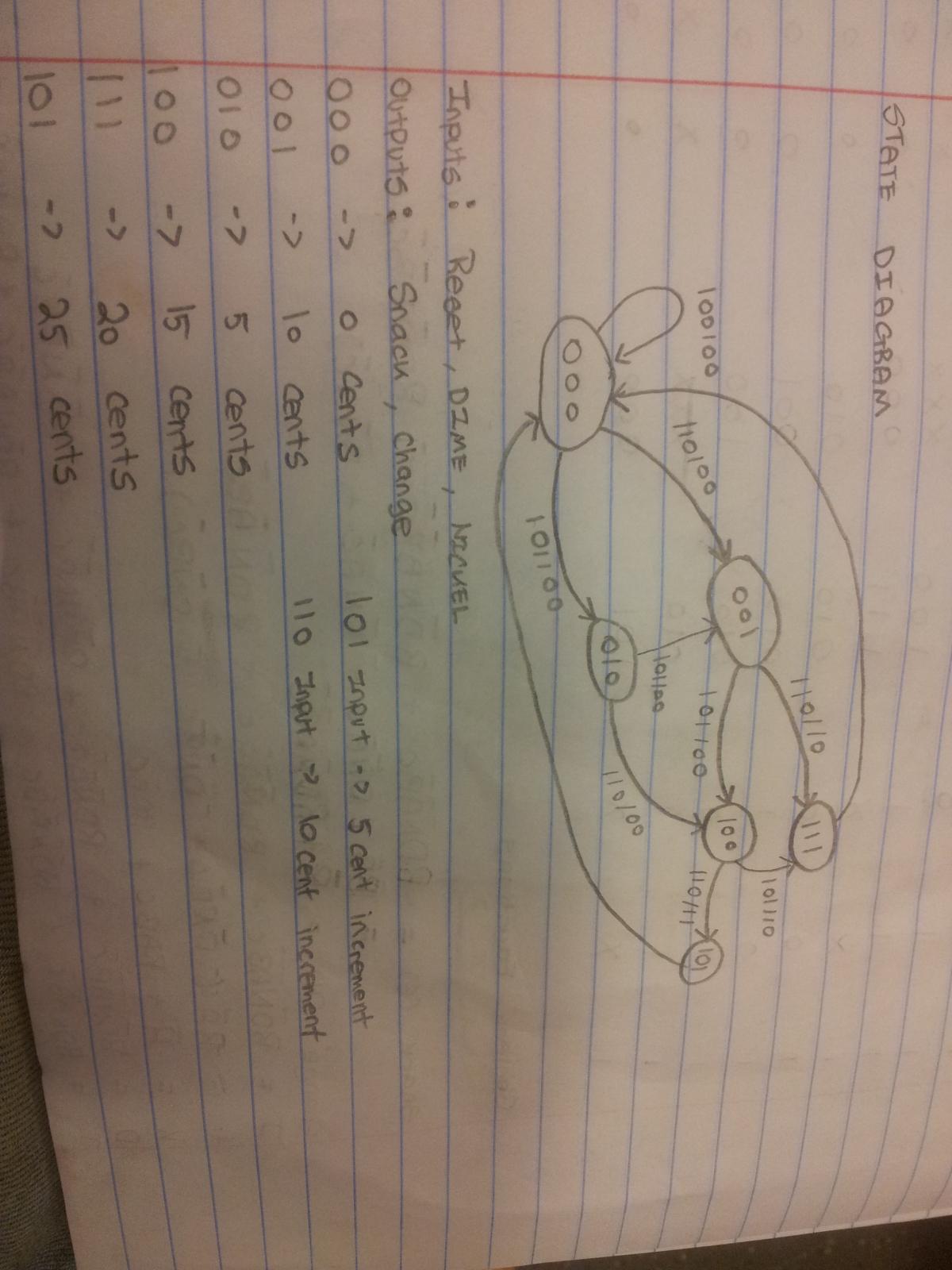
State Table enter image description here

The circuit was designed using a JK flip flop, D flip flop and T flip flop. (Had to use these because said so) and I end up with 32 situations that I have to account for which made the circuit very complicated (Could not use k-maps T_T). If anyone can give me an idea on how to simplify (not for the sake of homework, for my own knowledge as well), or rather reduce the amount of material in the truth table, would be great. Also I don't know how to integrate the asynchronous reset properly. If anyone needs any more information I'd be glad to give it to you.

\$\endgroup\$
4
  • \$\begingroup\$ One thing that may be causing confusion is the conflation of the concepts of "change" vs. "refund". If the user has inserted 5, 10 or 15 cents and then hits the reset, you need to refund the coins inserted so far (up to three nickels or a dime and a nickel). However, if he has inserted 15 cents and then inserts a dime, you need to dispense the snack and also a nickel change. \$\endgroup\$
    – Dave Tweed
    Commented Apr 8, 2013 at 15:54
  • \$\begingroup\$ Conceptually, the state machine only needs four states, to track whether 0, 5, 10, or 15 cents have been deposited so far towards a purchase. You do not need states for 20 or 25 cents, because the coins that would get you there should instead cause a snack (and possibly change) to be dispensed, taking you back to the "0 cents" state. \$\endgroup\$
    – Dave Tweed
    Commented Apr 8, 2013 at 16:01
  • \$\begingroup\$ Ok, but how can I do the logic from there? and how would I know if it's at 20 or 25 cents? Hmm, I think I might know what u are getting at. So i can reduce my states to 4, and use 2 variables, I see. How would I incorporate the asynchrounous reset from there? \$\endgroup\$
    – Aaron
    Commented Apr 8, 2013 at 20:16
  • \$\begingroup\$ I'd like to thank all the people that have replied to my question. @Dave Tweed, thank you! your state diagram exactly matched my new one. As for asynchronous reset, I have found out that they do not incorporate into the K-Maps since they are a direct input to the FF's. Therefore I was able to work this out with 4 variables, optimized it and came out with rather a simple circuit. Thank you all. The last problem is that I don't know who to give the answer too.. :) \$\endgroup\$
    – Aaron
    Commented Apr 8, 2013 at 23:35

2 Answers 2

3
\$\begingroup\$

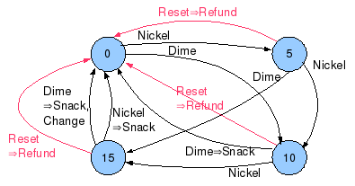
Without getting into the specific binary coding of inputs, outputs and states, the abstract state diagram should look something like this. The notation on each edge is Input→Output.

state diagram

Note that I have defined a third output "Refund" that refunds the coins inserted so far, which is a distinct operation from dispensing change along with a snack if 25 cents have been inserted.

Note that most real vending machines hold the coins that the user has inserted in a separate area until a snack has been dispensed, at which time, they are released into the actual coin box. If a refund is requested instead, the user gets his original coins back.

\$\endgroup\$
2
\$\begingroup\$

The asynchronous reset has caused you problems. Normally the way to do this sort of design is to do all the synchronous parts and then wire the reset up to flops individually. Normally the async reset goes to a separate pin on the flops. Check whether that's a valid interpretation of this question.

Having an output required when the reset input is asserted is a nasty requirement to implement "properly", but it doesn't say that you can't assert the "change" signal when there is no change and the "change" signal doesn't have to carry the value of the change, so you can just always assert the change output (=1) when reset is driven low.

It's not specified whether there is a clock signal at all or whether you're supposed to use the lower bit of DN to drive the clock pins. I'm going to assume the latter?

Once that's all out of the way, all you're doing is counting to 4. As soon as the count would go over 4, dispense and reset. If it hit 5, dispense change.

(I think you're meant to assert "dispense" and "change" on the transition 00 -> 11, and then deassert them and go to the next state on the falling edge 11 -> 00. Again this is underspecified).

\$\endgroup\$
2
  • \$\begingroup\$ Thanks for your reply, What do you mean by lower bit DN to drive the clock pins? Also for R (reset), it has to be part of the state table. The problem is that I cannot optimize this down to 4 variables which allows me to use K-maps. I currently have 6, RDNABC. \$\endgroup\$
    – Aaron
    Commented Apr 8, 2013 at 18:28
  • \$\begingroup\$ I have gotten it reduced. I just need to figure out how to incorporate the asynchronous reset properly T_T \$\endgroup\$
    – Aaron
    Commented Apr 8, 2013 at 20:23

Not the answer you're looking for? Browse other questions tagged or ask your own question.