0
\$\begingroup\$

to start off, honestly I just know simple circuits that's why I went on asking in this forum,

So basically I have a driving light that has two modes, high and low. It consists 3 wires. A black (gnd), red (low light), yellow (high light) wires. So this can be toggled if I used a 3 way switch. But I wanted to use a simple on and off switch to toggle between high and low beam. Is there a readily made circuit that I could use? Or can anybody point me to the right keywords on what to search?

So basically it goes like this:

  • Off switch : Off lights
  • On switch: High light
  • Off switch: Off light
  • On switch: Low light
  • Off switch : Off lights
  • On switch: High light
  • Off switch: Off light
  • On switch: Low light
\$\endgroup\$
2
  • \$\begingroup\$ That would be a very expensive switch (if you could find one.). Simple solution is a SPST switch for high beam only and the existing or another one for low beam. But trivial if you built a logic circuit and Relay to do it. It might be possible with relays with contact debounce caps ,. Maybe someone will design it for you for a beer. \$\endgroup\$
    – D.A.S.
    Commented Apr 24, 2021 at 15:53
  • 2
    \$\begingroup\$ Are you really happy for your headlights to turn off while you flick the switch twice to go between dip and high beam and similarly when switching back? \$\endgroup\$
    – Transistor
    Commented Apr 24, 2021 at 15:55

2 Answers 2

1
\$\begingroup\$

If we use a timing diagram to describe your requirements it becomes a lot clearer.

               ____      ____      ____      ____      ____      
Switch    ____|    |____|    |____|    |____|    |____|    |_____
               ____                ____                ____
High beam ____|    |______________|    |______________|    |_____
                         ____                ____
Dip beam _______________|    |______________|    |_______________

schematic

simulate this circuit – Schematic created using CircuitLab

Figure 2. Implementation using a bi-stable latching relay.

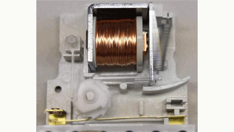
A bi-stable latching relay would be a simple solution.

enter image description here

Figure 3. Go to HomoFaciens and click "Start animation" to see how the pawl mechanism is advanced on every impulse of the relay coil.

The relay shown in Figure 3 will be a low current device so typically we would use that to drive a heavier duty relay to control the lights. I have not shown the additional relay in Figure 2.

If this circuit is for a car it seems like a very poor idea as the lights will go off during every transition from low to high and back again.

\$\endgroup\$
0
\$\begingroup\$

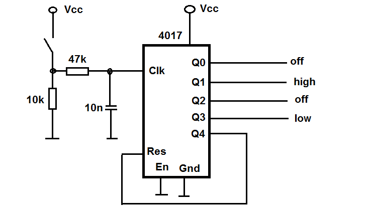
It can be build with 4017 IC connected as ring counter with 4 states, at 5th state reset to 1st. The off outputs dont have to be connected. If your wires are power lines (not just logic sig.) you must insert transistor/relays to outputs.

enter image description here

\$\endgroup\$
1
  • \$\begingroup\$ A small point: the 4017 doesn't power up with Q0. You need to reset on power-up otherwise it could start on 5 and you'll have to step through to wrap around to Q0 again. One way would be to have diodes from Q4 - Q9 all feeding into RES. \$\endgroup\$
    – Transistor
    Commented Apr 24, 2021 at 17:18

Your Answer

By clicking “Post Your Answer”, you agree to our terms of service and acknowledge you have read our privacy policy.

Not the answer you're looking for? Browse other questions tagged or ask your own question.