0
\$\begingroup\$

These are the relays I have: https://www.amazon.com/dp/B07QXXNGHR

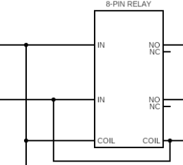
So simply put, the circuit I'm trying to complete is using a single 24V/8A source, and one of my suspicions as to the trouble I'm having is in the way that I'm attempting to energize the coil and feed the commons with the same power source. So I'm piggybacking the coil and commons(IN) on the same feed, if that makes sense.

Is there an inherent problem with using the same power source to feed both of these parts of the relay? enter image description here
\$\endgroup\$
6
  • \$\begingroup\$ What problem are you having? That should work fine. What happens if you try it without the load attached? \$\endgroup\$
    – Drew
    Commented Feb 6, 2023 at 0:37
  • \$\begingroup\$ Thanks. Well, then that means my problem is more complicated than I thought. It would not be simple to explain the problem I'm having unfortunately lol I'll start breaking down my circuit and isolating parts to definitively identify the problem, but your confirmation is very helpful, so thank you again. \$\endgroup\$
    – tinkering
    Commented Feb 6, 2023 at 0:49
  • \$\begingroup\$ How are you driving the coil? \$\endgroup\$
    – Polynomial
    Commented Feb 6, 2023 at 1:00
  • \$\begingroup\$ The relay seems redundant to me - it will operate when 24 volts is applied between the relay "In" terminals, connecting those terminals to the NO terminals - why not just connect the 24 volt source to whatever is connected to the NO terminals? \$\endgroup\$ Commented Feb 6, 2023 at 1:00
  • \$\begingroup\$ Fair questions, but the only intention behind this post was to clarify that the way I'm feeding this coil is acceptable. The coil is being fed from a DPDT switch from the aforementioned 24V8A source. \$\endgroup\$
    – tinkering
    Commented Feb 6, 2023 at 1:03

2 Answers 2

0
\$\begingroup\$

I don't see a problem with doing that, but I also don't see a point of having the relay, then.

Whenever 24 volt power is available the relay will pick up and connect it to the output pins. It might as well not be there.

Most people would want to have something interrupt current to the coil so that the relay disconnects from time to time. I presume that is coming?

The only issue I can see here is if the load is high-current and the run from the supply is long and with thin wire. The voltage drop could cause the coil to drop out. We see that one a lot when someone tries to power the controller from the motor supply.

\$\endgroup\$
1
  • \$\begingroup\$ This is a zoomed in view of the circuit overall, my intention was to validate that this method of energizing the coil and feeding the commons was valid. The relay is necessary in the broader scheme of the overall circuit. but it's perfectly understandable why anyone would question its usage given the view I've provided. I've actually posted a new question with a picture of the whole schematic (I didn't want to crowd this post with too much info, nor did I want to sway from the point of this post which was a very simple question). Thank you for your input though. V drop would be surprising here \$\endgroup\$
    – tinkering
    Commented Feb 6, 2023 at 1:57
0
\$\begingroup\$

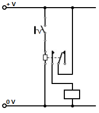
One of the purposes of using a relay could be to enable a low current device to switch a high current load e.g. a low current dashboard switch for a headlight or a low current steering mounted switch for a horn in an automobile.

It could also be to enable a low voltage device to switch a high voltage load for reasons of safety.

There should be no problem in using the same low-voltage source for the relay coil as well as the load.

enter image description here

\$\endgroup\$

Your Answer

By clicking “Post Your Answer”, you agree to our terms of service and acknowledge you have read our privacy policy.

Not the answer you're looking for? Browse other questions tagged or ask your own question.