33
\$\begingroup\$

I'd like to use an Arduino Uno R3 battery powered a datalogger. I want do supply it directly with a Step-Up regulated 5V rechargable battery powersource at power pin 5V.

I don't want to suppy it with 5V at the PowerJack or Vin because it's not necessary an would result in lower voltage when powered with 5V at Vin and unnecessary power dissipation at U1.

Let's take a look at the schematic: http://arduino.cc/en/uploads/Main/Arduino_Uno_Rev3-schematic.pdf

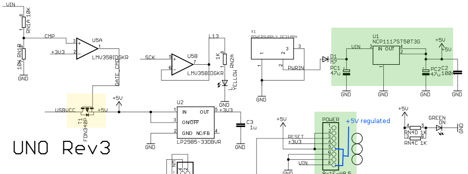
I've edited it, take a look at the green areas and blue paths (ignore the yellow area at first):
enter image description here

Just supplying it at that pin 5V however might destroy the linear regulator U1 that regulates >5V+ Vin down to 5V, I fear.

Question

  • Is it acceptable and safe to suppy regulated 5V+ to pin 5V?
  • Should I additionally short it to Vin?

Unfortunately there's no internal schematic for U1 (NCP1117ST50T3G) in the datasheet.

For interest

Take a look at the yellow area: am I wrong or is the protection diode reversed? Shouldn't it have the catode at USBVcc?

Edit 1:

As three answers state that it would be the safest way supplying the Arduino with regulated 5V though USB, let I should clarify my question a bit: I'd like to fit the setup within a small case, so I want to avoid plugging in a USB cable if possible.

Except for testing purposes where this might happen by accident, it's not possible that Vin/VccUSB and Vcc 5V are available at the same time.

\$\endgroup\$
2
  • \$\begingroup\$ I am planning to do the same thing, so I ask: in the end did you use the 5V pin or the USBVCC pin, or something else? \$\endgroup\$ Commented Apr 1, 2015 at 18:25
  • \$\begingroup\$ I came across a situation where my circuit works using external power, but stops working correctly with the USB hooked up. To allow USB connection and still have proper behavior, I used hot air to lift the fuse off the Uno. It's the gold looking thing next to USB port and its labeled 501H. \$\endgroup\$
    – Krista K
    Commented May 28, 2015 at 22:59

7 Answers 7

16
\$\begingroup\$

Here's a less formal way to look at it: Providing power directly to the +5V pin is (almost) exactly what happens when the Uno is powered over USB. As USB power is perfectly fine, by design, then your setup should be OK too.

External regulated +5V can be supplied to the USBVCC net just as well, for example by using an USB-B cable.

As per the second question, you should not connect to V_in. NCP1117's output may then become an alternative, competing power-source and this is best to be avoided.

\$\endgroup\$
3
  • 1
    \$\begingroup\$ "Providing power directly to the +5V pin is (almost) exactly what happens when the Uno is powered over USB" -- You're right. Thanks for opening my eyes. :) \$\endgroup\$ Commented Apr 18, 2013 at 19:20
  • \$\begingroup\$ After comparing the answers, I think your answer matches my question best, so I've accepted your answer. (But I should say that "by design" in your answer should be emphasised - my PC supplies only 4.85V ;) \$\endgroup\$ Commented Apr 18, 2013 at 19:36
  • \$\begingroup\$ Thanks :) The USB specification defines the allowed voltage as 5V +/-5%, so every USB device should be able to handle any voltage from 4.75V to 5.25V. Alternatively, a power supply that outputs a regulated voltage in this range, can be used to power an USB device (as long as it can supply enough current). \$\endgroup\$
    – DimKo
    Commented Apr 19, 2013 at 9:00
14
\$\begingroup\$

The official stance on supplying power directly to the 5V pin on the Arduino Uno is thus:

5V. This pin outputs a regulated 5V from the regulator on the board. The board can be supplied with power either from the DC power jack (7 - 12V), the USB connector (5V), or the VIN pin of the board (7-12V). Supplying voltage via the 5V or 3.3V pins bypasses the regulator, and can damage your board. We don't advise it.

That being said, supplying regulated 5 Volts to the VUSB connector (not broken out as a pin, AFAIK) should be the way to go: This is how the board is normally powered when running off an USB cable, so evidently the voltage drop is acceptable.

Further, the only voltage drop to the +5V line when taking power from VUSB is the drop across the on-resistance of the FDN340P MOSFET, between 70 and 110 mOhms. For typical operations which do not involve driving high currents off the Uno, a current demand of 100 mA would result in a voltage drop of 11 mV, by a rough estimation.

For a simple way to power VUSB, just liberate an USB cable by cutting it open, and apply the 5 Volts across the VUSB and ground pins.

\$\endgroup\$
6
  • \$\begingroup\$ Thanks for the citation, I must have overlooked it because I was looking for this on that page too. The phrase "via the 5V or 3.3V" is abit misleading, however. Bypassing might really damage U2, but as you, DimKo and Passerby say, bypassing 5V via T1 is what a USB-powered Arduino does. \$\endgroup\$ Commented Apr 18, 2013 at 19:41
  • \$\begingroup\$ See my Edit 1 too, I'd like to avoid plugging in a USB cable. I think I'll power the Arduino through the 5V pin (at my own risk ;). \$\endgroup\$ Commented Apr 18, 2013 at 19:43
  • \$\begingroup\$ +1 for "For a simple way to power VUSB, just liberate an USB cable by cutting it open, and apply the 5 Volts across the VUSB and ground pins." Great idea. \$\endgroup\$ Commented Oct 19, 2013 at 18:47
  • \$\begingroup\$ Not sure what this "VUSB" net refers to. I'm assuming you mean either pin 1 of the USB connector (I see that's "XUSB" on UNO) or the "USBVCC" net? \$\endgroup\$
    – gwideman
    Commented Apr 26, 2014 at 12:39
  • \$\begingroup\$ @gwideman Yes, USBVCC is referred to as VUSB on many Arduino schematics, and that conductor has a screen printed label of VUSB on my board as well. \$\endgroup\$ Commented Apr 26, 2014 at 14:07
13
\$\begingroup\$

Not recommended officially

Arduino (the company) does not recommend directly supplying 5 volts in, because:

  1. The target audience doesn't always understand how the schematic is designed, and as beginners/non-techs, would likey cause something bad to happen, like connecting an unregulated 5 volts to the 5V line, and blowing things, causing customer service calls/refunds/repairs/etcetera.
  2. Directly supplying 5 volts bypasses the auto-sensing/voltage protection method.

How Arduino's USB/external power selection works

Supplying 5 volts directly is easy. USB power practically does this, as does the ICSP protocol/header. USB has a 500mA PTC fuse on the line, and has a p-channel mosfet, which by themselves do not offer any protection. But there is also the LMV358 labeled U5A, above that mosfet. It is (half) an opamp, being used as a comparator. If VIN is detected, and higher than 3.3 volts, the opamp drives the line low, disabling the mosfet, cutting the USBVCC off from the 5V line. This makes it so that you can use VIN and USBVCC at the same time without problems. Otherwise you would have two power sources competing on the same rail (USB and the 5 volt regulator).

The mosfet has a body diode

It's part of the mosfet construction, internal, and functions as reverse voltage protection, preventing the 5V power rail from back flowing to the USBVCC. It is disabled when the mosfet is on, and reversed biased when off.

Warnings

  1. DO NOT CONNECT USB AND YOUR 5V AT THE SAME TIME!
    By inputting a regulated 5 volts in at the 5V pin, you skip the helpful power source selection mechanism. You can just as easily connect your 5 volt in to the USB connector, or between the USB connector and the USB PTC fuse, but that will cause you to have a 500mA limit. If you need more current, you can bypass the fuse, but not the mosfet.
  2. DO NOT SHORT 5V to VIN!
    The 5 volt regulator in any case, will be just dandy, as long as VIN is not used.
\$\endgroup\$
7
  • \$\begingroup\$ Regarding the ICSP (and ISP) headers: The pin that's connected to the +5V net is ISP VTG, which is intended for the target device (here Arduino) to supply power to the programmer, which allows the programmer to accommodate to +5V or +3.3 targets. It's not intended as an input for 5V, so it's not evidence in favor of connecting a 5V supply to the +5V net. (Though not strongly against either.) \$\endgroup\$
    – gwideman
    Commented Apr 26, 2014 at 12:48
  • 1
    \$\begingroup\$ "If VIN is detected, and higher than 3.3v, the opamp drives the line low": Actually there's a voltage divider between VIN and CMP input to U5A, which means that VIN has to be higher than 6.6V to disable USBVCC as an input. Further, since there's a diode between the power input jack PWRIN and VIN, (adding say 0.6V drop) and NCP1117's dropout is 1 to 1.2V, that means the external supply should be above 7.2V to shut off USBVCC, even though without USBVCC the external supply could supply reliable power down to 6.6 to 6.8V \$\endgroup\$
    – gwideman
    Commented Apr 26, 2014 at 12:58
  • \$\begingroup\$ But I do concur that connecting a 5V supply to the Arduino shield +5V will work, but as Passerby emphasizes, the user has to be sure not to connect that supply AND USB at the same time. A possible result of connecting both would be to damage either the USB host, the external supply, or preferably, blowing of fuse F1. \$\endgroup\$
    – gwideman
    Commented Apr 26, 2014 at 13:02
  • \$\begingroup\$ @Passerby You answer explains in good dummy language what is going on. However I don't quite understand what you would like to say with "Diode on the mosfet, is a Body Diode". My best guess is something like: Although the Mosfet contains a diode that normally would protect currents from flowing into the direction of the USB host, this internal diode (protection) is disabled as soon as voltage is applied to Arduino its "USBVCC". \$\endgroup\$
    – Pro Backup
    Commented Feb 8, 2016 at 22:54
  • 1
    \$\begingroup\$ @Bozzy With the MOSFET off, current can still flow through the MOSFET's diode from USBVCC to +5V. However, that current will be tiny, because in this scenario (>6.6V at VIN) we have +5V supplied from regulator U1 to the +5V line. Thus there will be no (or very little) voltage drop across that diode, hence very little current. The diode would need a forward drop of say at least 0.4V and more like 0.6V for appreciable current through it. \$\endgroup\$
    – gwideman
    Commented Apr 28, 2020 at 9:12
4
\$\begingroup\$

I think you should be fine.

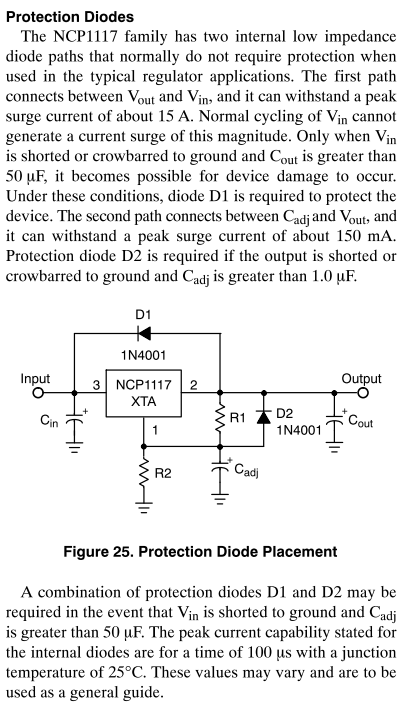
From the NCP1117 datasheet, page 10:

enter image description here

From the sound of the datasheet, the regulator has internal protection diodes that should easily be able to handle the capacitive loading present on VIN (from the look of it (and screw you, net labels and non-searchable schematic), the total capacitance across VIN is 47 uF).

As such, even if all the capacitors on the board are fully discharged, the only current that will flow through the regulator's protection diodes is the current required to charge that single 47 uF capacitor.


If you're really concerned, or want to be extra cautious, you can put a Schottky diode between the 5V pin and the Vin pin. This will prevent any reverse-current from flowing through the regulator (basically, this is the same as D1 in the above diagram).

You could also simply jump the Vin pin to the 5V pin, and just feed 5V into the DC-in jack. Be aware that if you feed the arduino with more thn 5.5V, you will damage something.

\$\endgroup\$
3
  • \$\begingroup\$ Who is downvoting this? And why? \$\endgroup\$ Commented Apr 15, 2013 at 22:27
  • \$\begingroup\$ The datasheet excerpt I posted clearly says the part has an internal protection diode from the output to the input. It may not be a good practice to use it like this in a production setting (I wouldn't), but the only thing it could even damage would be the voltage regulator, which isn't being used in this situation anyways. \$\endgroup\$ Commented Apr 15, 2013 at 22:29
  • 1
    \$\begingroup\$ I've +1'ed you for a thoughtful and on-point answer. That said, I think on balance that supplying the external +5V power to the USB connector is the best way to go, as it precludes accidental connection of external +5V simultaneously with USB power, and takes advantage of F1. \$\endgroup\$
    – gwideman
    Commented Apr 26, 2014 at 13:10
3
\$\begingroup\$

Another idea might be to connect a 2.2k resistor from +5v to the point labeled "CMP" which is the non inverting input to the op amp pin 3. This will disable the USB +5v power to the board but still allow USB communications.

Of course a SPST switch to turn 'off' the resistor would be nice too so you could disable this new feature. The switch would be wired in series with the 2.2k resistor. If you never plan to use USB power again however the switch wont be needed, only if sometimes you have to power the board with the USB power with no external +5v power input.

Whatever you do test to make sure it works by measuring the output of the LM358 when you connect the external +5v supply.

\$\endgroup\$
1
\$\begingroup\$

Supplying 5 volts directly is easy. USB power practically does this, as does the ICSP protocol/header. USB has a 500mA PTC fuse on the line, and has a p-channel mosfet, which by themselves do not offer any protection. But there is also the LMV358 labeled U5A, above that mosfet. It is (half) an opamp, being used as a comparator. If VIN is detected, and higher than 3.3 volts, the opamp drives the line low, disabling the mosfet, cutting the USBVCC off from the 5V line. This makes it so that you can use VIN and USBVCC at the same time without problems. Otherwise you would have two power sources competing on the same rail (USB and the 5 volt regulator).

Hmm, isn't this backwards? The voltage divider is connected to the non-inverting input of the comparator, and so drives it HIGH (+5V) when the divider voltage is above 3.3V, and LOW when it is below 3.3V. The P-channel enhancement-mode MOSFET is switched OFF when the gate voltage is HIGH (i.e. Vgs = 0V) and switched ON when the gate voltage is LOW (i.e. Vgs = -5V).

The result is the same (a voltage above 3.3V at the divider turns the MOSFET off and isolates the USB power, and a low voltage at the divider connects USB power to the circuit) as the quoted paragraph states - but I think the voltages stated there are backwards.

\$\endgroup\$
-1
\$\begingroup\$

I think the best to do in that case is powering the arduino through +5V Pin from a 5V regulated source and, if ever needed to plug USB to code or print values to computer, use a USB cable with its 5V wire cuted off.

That way you will never put your arduino in a power source fight neither. But you won't have its 3.3V pin workin. Right?!, because 5V rail do not go to 3.3 voltage regulator.

\$\endgroup\$

Your Answer

By clicking “Post Your Answer”, you agree to our terms of service and acknowledge you have read our privacy policy.

Not the answer you're looking for? Browse other questions tagged or ask your own question.