4
\$\begingroup\$

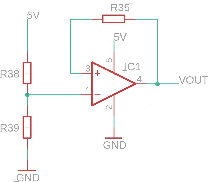
I would like to find a formula to find Vout in this circuit:

enter image description here

I already used the concepts of virtual ground and V+ = V-, but I can't get a formula for Vout that depends on VCC (5 V) and the values ​​of the resistors. Could someone explain to me how to analyze this?

\$\endgroup\$
3
  • 1
    \$\begingroup\$ But V+ is not V- in this circuit. Does it help? I don't think anyone can find what Vout is. \$\endgroup\$
    – Justme
    Commented Apr 11, 2023 at 22:21
  • 1
    \$\begingroup\$ You cannot apply the concept of virtual ground there, because this can be applied only when the op amp works in the linear region, which is usually not the case with positive feedback (not impossible, but not in this case). \$\endgroup\$ Commented Apr 12, 2023 at 9:03
  • \$\begingroup\$ Virtual ground is not a rule. It's a shortcut so you can skip some mathematical analysis for specific circuit configurations where the opamp is wired to hold one node at the same potential as another node. You can't just label something as virtual ground just because an opamp is there. Really, you don't need the concept of virtual ground at all. If it is valid it comes out in the analysis anyways. \$\endgroup\$
    – DKNguyen
    Commented Apr 12, 2023 at 14:33

4 Answers 4

7
\$\begingroup\$

One of the first questions you have to ask when dealing with op-amps is "which model shall I use?". In this question, I'll go with the one that says that an op-amp has infinite gain, no loading on the input pins no matter what, and an output that saturates at the rail voltages (so, ground and +5V, in this case).

If, when the power is turned on, whatever transients that happen cause the \$v^-\$ input to be higher than the \$v^+\$ input when the op-amp starts working, the op-amp will pull the output down to ground. Then it will stay there forever, because \$v^+\$ has been pulled lower than \$v^-\$ and there's nothing to change that circumstance.

If, when the power is turned on, whatever transients that happen cause the \$v^-\$ input to be lower than the \$v^+\$ input when the op-amp starts working, the op-amp will pull the output up to +5V. Then it will stay there forever, because \$v^+\$ has been pulled higher than \$v^-\$ and there's nothing to change that circumstance.

Google "comparator" and "hysteresis" for more detailed information.

\$\endgroup\$
5
\$\begingroup\$

This is a bistable circuit. Assuming resistors R38 & R39 are sized such that the (-) pin of the op-amp is within the common-mode range of the op-amp, the positive feedback causes the output of the op-amp to be either at the (+) rail or the (-) rail.

Lots of caveats here. Much depends on the actual op-amp itself. Many op-amps can't swing to one or both of the supply rails. But in general, the output will be either HI or LO.

\$\endgroup\$
4
  • \$\begingroup\$ Why can the output be HI or LO? Can it be proven mathematically? \$\endgroup\$
    – WalterPH
    Commented Apr 11, 2023 at 22:52
  • 2
    \$\begingroup\$ @WalterPH mathematically it should be infinite volts or negative infinite volts \$\endgroup\$ Commented Apr 12, 2023 at 0:14
  • \$\begingroup\$ @WalterPH: Any time the + input exceeds the - input by a detectable amount, the device will try to increase the output voltage if it can. Any time - exceeds plus, the device will try to decrease the output voltage if it can. A device's ability to pull the output high will generally diminish as the output approaches the positive rail, and the ability to pull low will diminish as the output approaches the negative rail. \$\endgroup\$
    – supercat
    Commented Apr 12, 2023 at 15:37
  • \$\begingroup\$ @WalterPH: In theory, an op amp could include a DC-to-DC converter, which would pass some current from the positive rail straight through to the negative rail, and harvest the energy thereof to output a voltage which is higher than the positive rail or lower than the negative rail, but in practice if one needed e.g. use a 5-volt power supply to produce an output swing of +/- 9 volts, one would use a couple of DC-to-DC converter to produce +/- 10 volt rails, and then use those to power an op amp. \$\endgroup\$
    – supercat
    Commented Apr 12, 2023 at 15:41
5
\$\begingroup\$

With positive feedback the open loop gain will just amplify (and saturate) the output according to differential voltage (not zero) at the inputs.

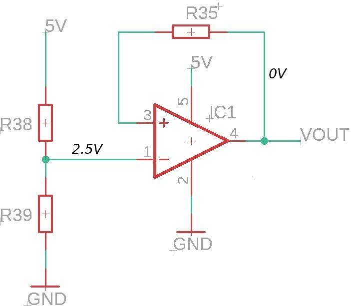
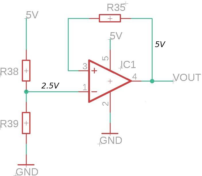
Assuming (for simplicity) that R38 = R39 and that the output can saturate to the voltage rails, both situations are possible:

enter image description here

enter image description here

In the first case the negative differential voltage is amplified and in the second case the differential voltage is positive. Both saturate to whatever are the limits of the opamp and the input common mode voltage specification could also be violated.

\$\endgroup\$
3
  • \$\begingroup\$ Your answer is very clear and I could repeat many times until I memorize it, but I would like to understand why the output of the opamp saturates? and why can the output be HO or LO? Could you explain it a bit, please? \$\endgroup\$
    – WalterPH
    Commented Apr 11, 2023 at 22:51
  • \$\begingroup\$ The opamp will amplify the differential voltage at the inputs (V+ - V-) by a very large open loop gain. The output range (the maximum and minimum values) are specified at the datasheet, usually related to the voltage rails. To understand why it saturates, you must see the internal schematic of the component to realize that the output is limited by the way the output stage is built. \$\endgroup\$
    – devnull
    Commented Apr 11, 2023 at 22:54
  • \$\begingroup\$ @WalterPH The output saturates because there is no negative feedback loop to its inverting input, making it amplify the input voltage difference between its inputs MANY thousands of times (typically about 100,000 times), turning even a 1mV difference into 100V at the output, but since most op-amps don't work at higher than around 30+ volts (5V in your case), the output would just saturate to the supply voltage. Additionally, the op-amp in your circuit has a POSITIVE feedback, making it even more certain to saturate. \$\endgroup\$ Commented Apr 11, 2023 at 23:44
1
\$\begingroup\$

Quote: I already used the concepts of virtual ground and V+ = V-, but I can't get a formula for Vout that depends on VCC (5 V) and the values ​​of the resistors. Could someone explain to me how to analyze this?

Is there any mathematical problem to use "the concepts of virtual ground and V+ = V- " ? No, it is very simple to apply the equation V+=V-.

Because of an infinite input resistance for the opamp there will be no current through the feedback resistor and we have V+=Vout=V-=+2.5V (assuming R38=R39)

Anything wrong? YES !

I have used the virtual ground concept which is allowed for negative feedback only !"

Comment: One should know that simulation programs will make the same error for DC analyses (incl. operating point determination). For revealing the instability a simulation in the time domain (TRAN) is necessary with a power supply switched on at t=0.

To be exact: The simulation program does not really make an error - it assumes that (a) all power supplies are on (without any switching effects) and (b) that there is absolutely no external disturbing effect (thats what we assume during calculation). In such an ideal case (which never can happen) the circuit would be stable. Insofar, the simulation program is correct - but the users interpretation is wrong.

\$\endgroup\$

Your Answer

By clicking “Post Your Answer”, you agree to our terms of service and acknowledge you have read our privacy policy.

Not the answer you're looking for? Browse other questions tagged or ask your own question.