1
\$\begingroup\$

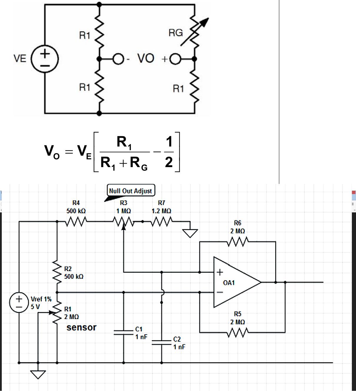
In this question/answer theres this op-amp circuit:

enter image description here

I can't work out whats happening. At a glance the op-amp circuit looks like a cross between a schmitt trigger, differential amplifier and possibly an oscillator! Help!

What is it? What could ut be used for? How does it work? Please assume working knowledge of op-amps but not harder math such as calculus, transfer functions etc

\$\endgroup\$
2
  • 3
    \$\begingroup\$ Start by determining the transfer function for the op amp. \$\endgroup\$ Commented Feb 25, 2018 at 12:27
  • \$\begingroup\$ @Tony Stewart. EE since '75 you need to explain this circuit. Good luck! \$\endgroup\$
    – Andy aka
    Commented Feb 25, 2018 at 19:44

2 Answers 2

1
\$\begingroup\$

It's a diff amp comparing the fixed value off the offset / null and the value of the sensor. The two 2k resistors look like atlantic attempt at hysteresis but don't seem like very good values.

\$\endgroup\$
1
\$\begingroup\$

Without going through the equations it’s hard to tell what’s going on with that circuit and which feedback branch dominates, but the only times I have seen similar things is when people make mistakes.

I once saw an electronics magazine publish a “non-inverting amplifier configuration” for audio applications that just mirrored the resistor location of the inverting one (thus creating a Schmitt trigger).

\$\endgroup\$

Your Answer

By clicking “Post Your Answer”, you agree to our terms of service and acknowledge you have read our privacy policy.

Not the answer you're looking for? Browse other questions tagged or ask your own question.