0
\$\begingroup\$

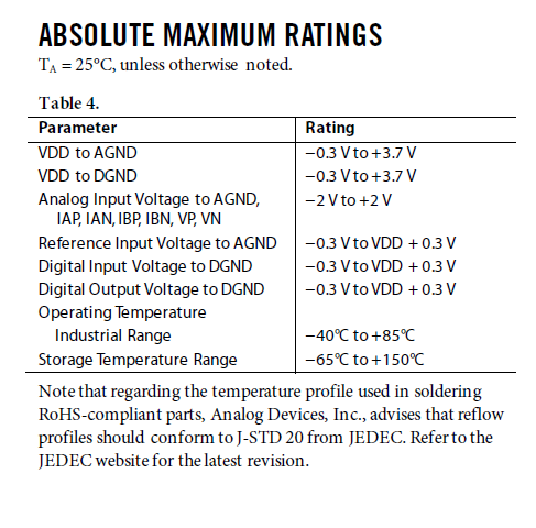
I am currently designing a power measuring board that incorporates ADE7953 and ESP-32 microcontroller, however although i have read the Datasheet document for ADE7953 and searched online forums I am confused on certain pin connections regarding the ADE7953 chip, from the Datasheet it states that VP and VN has a maximum differential voltage range of +/-500mV and analog input voltage to AGND of +/-2V however from all the schematics that are shown the live 220V AC is directly fed to VP and VN, how is this possible? dont we need a voltage devider circuit or a transformer inbetween the line voltage (220V AC) and VP and VN? is there any schematics that you can provide to better understand the logic behind it?

The datasheet of ADE7953 that i am refering to is ADE7953 Datasheet

One of the sample schematics is as follows from the ADE7953 Datasheet file Sample Schematics
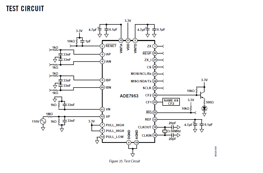
And from the same Datasheet the absolute maximum input values are as follows: enter image description here
\$\endgroup\$
4
  • 1
    \$\begingroup\$ Please link the data sheet. \$\endgroup\$
    – Andy aka
    Commented Apr 12, 2023 at 16:56
  • \$\begingroup\$ I can guarantee that 220V isn't going into the chip can you post a pic of the schematic (and provide a source link from where you got it) \$\endgroup\$
    – Voltage Spike
    Commented Apr 12, 2023 at 17:40
  • \$\begingroup\$ @Andyaka i updated my question, kindly check it \$\endgroup\$
    – BulBul
    Commented Apr 12, 2023 at 17:42
  • \$\begingroup\$ @VoltageSpike i updated my question, from the schematic i see a voltage divider circuit and a capacitor to smooth the signal at terminal VP (please correct me if i am wrong), however shouldn't we at first limit the current from the 110V source? by a current limiting capacitor and a shunt resistor then feed the output to the voltage divider circuit? \$\endgroup\$
    – BulBul
    Commented Apr 12, 2023 at 17:45

1 Answer 1

2
\$\begingroup\$

The Vp has a voltage divider with a ratio of 1000:1 so 110V will end up being ~0.1 on the output of the voltage divider. If you want 220V, use a 2000:1 resistor divider (so use 500Ω instead of 1k)

If using this in a PCB circuit make sure creepage and clearances are being followed.

\$\endgroup\$
6
  • \$\begingroup\$ what about the power dissipation at the two resistors of the voltage divider circuit? shoudn't we use a current limiting circuit before the voltage divider circuit? \$\endgroup\$
    – BulBul
    Commented Apr 12, 2023 at 17:57
  • \$\begingroup\$ 220V with a 1MegΩ reistor is 50mW so that could get warm, I guess you could use a 2MegΩ resistor which would be 25mW, the higher the resistance, the more error you'll get because the Vp pin has a 540kΩ input resistance \$\endgroup\$
    – Voltage Spike
    Commented Apr 12, 2023 at 18:03
  • \$\begingroup\$ Thanks for your reply and clarifications, as a final confirmation before i start designing my PCB, as a person of expertise in the field do you confirm that this is the proper way of connecting live 220V AC terminal to the ADE7953 chip? \$\endgroup\$
    – BulBul
    Commented Apr 12, 2023 at 18:24
  • \$\begingroup\$ What do you mean by proper? \$\endgroup\$
    – Voltage Spike
    Commented Apr 12, 2023 at 18:33
  • \$\begingroup\$ I mean obviously you know better than me, maybe there are better ways that you might be aware of for such scenarios, based on your knowledge is this a good design to build my PCB on? i want to use the best approach on the PCB design. \$\endgroup\$
    – BulBul
    Commented Apr 12, 2023 at 18:40

Your Answer

By clicking “Post Your Answer”, you agree to our terms of service and acknowledge you have read our privacy policy.

Not the answer you're looking for? Browse other questions tagged or ask your own question.