I have created a PCB with a microcontroller (3.3V logic) and a 1.14-inch TFT display.
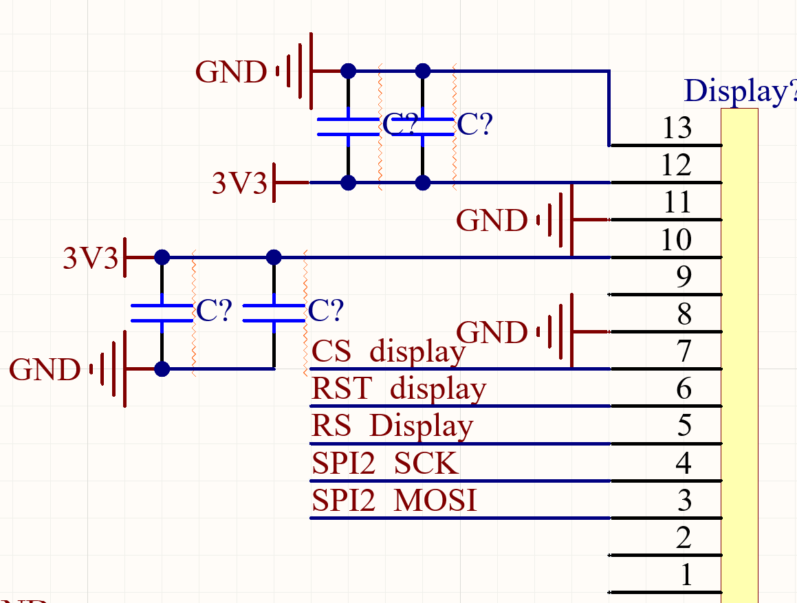
The circuit I have right now powers the display, and it works great with the PCB I ordered!
However, I now need to be able to control the power supply to the display using the microcontroller. Currently, it's taking its power directly from the battery. Here's what I want:
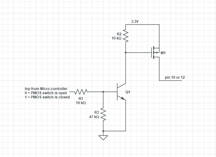
Pin 12 of the display: Controlled by an output pin of the microcontroller. When there's 0 V at the output pin, pin 12 should not be able to draw any current, hence it should be an open circuit. When there's 3.3V at the output pin of the microcontroller, I want pin 12 to act just like in the circuit above, with a connection to the 3.3V (power supply battery).
The same goes for pin 10 of the display: Controlled by another output pin of the microcontroller. When there's 0 V at the output pin, pin 10 should not be able to draw any current, hence it should be an open circuit. When there's 3.3V at the output pin of the microcontroller, I want pin 10 to act just like in the circuit above, with a connection to the 3.3V (power supply battery).
The purpose of this is to completely shut down the display to ensure it does not draw any current. When 0 V is at the output pins of the microcontroller, the microcontroller is in sleep mode, and it should be able to remain like that for a month without the display or transistor drawing any current.
How should I solve this? I see there are solutions using both bipolar transistors and MOSFETs. What is the best solution in my case? Is there perhaps any other way to make this work?
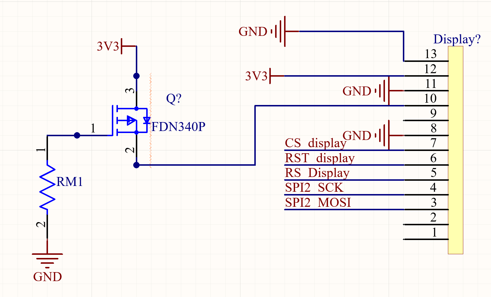
Could this be a solution to my problem? (And of course to the same thing with PIN 12). The gate will be connected to the microcontroller output.


